

TL;DR #
High-speed carton packaging machines operating at 500 packs/min generate fault frequencies exceeding 61 incidents per month when compensation mechanism bearings and conjugate cam assemblies are worn — a direct hit to line efficiency and finished-pack presentation quality. For packaging buyers, this means that carton structure, surface finish integrity, and registration accuracy on printed tobacco-style packaging are all downstream consequences of mechanical precision upstream in the forming equipment. Before approving any high-volume carton packaging program, verify that the supplier’s equipment maintenance protocol includes zero-clearance cam adjustment and phase-verified compensation motor calibration.
Overview #
The mechanical reliability of high-speed carton packaging equipment is not an abstract engineering concern — it directly determines whether the printed surface, folded structure, and registered graphics on your finished cartons hold up at production scale. Field evaluation data from a cigarette-industry equipment maintenance program at a large-scale manufacturing facility in Yunnan Province provides a detailed breakdown of how transmission system failures cascade into pack shift, misalignment, and clamping faults at the critical transfer point between the drying conveyor and the output wheel assembly. The study tracked fault frequency across three consecutive production months, comparing pre- and post-intervention performance across a single GDX500 packaging line running at 500 packs/min.
What makes this analysis useful beyond the tobacco sector is its specificity: the failure modes documented here — phase drift in compensation mechanisms, bearing wear in eccentric assemblies, cam-roller clearance growth — are characteristic of any high-cycle rotary packaging machine. If you are buying custom paper boxes or gift packaging solutions at volume, the same mechanical variables govern whether your folded cartons arrive with consistent crease registration, tight corner forming, and undamaged surface finish.
This article uses that maintenance case data as a technical reference point for understanding what equipment-level precision requirements actually look like in a production environment — and what packaging buyers should be asking their suppliers to demonstrate.
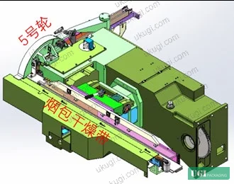
Transmission System Failures in High-Speed Digital and Mechanical Packaging Equipment #
To understand how mechanical fault modes affect print and packaging quality, you need to understand the transmission chain. In the GDX500 system, the conveyor belt and the 5th wheel output station are driven from a single shared transmission system. That system consists of:
- A primary drive pulley
- A cigarette pack conveyor drive mechanism built around a conjugate cam intermittent mechanism
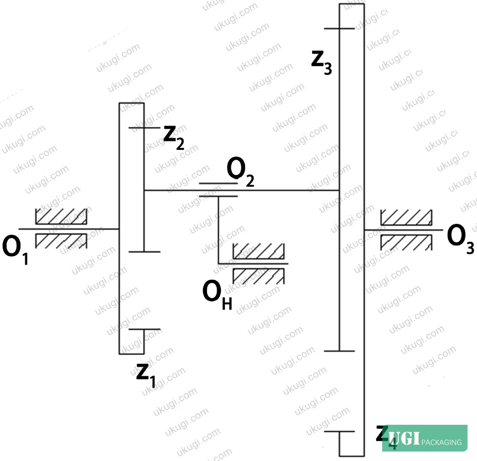
- An internal gear speed-change mechanism (worm gear + eccentric seat + internal gear cluster)
- A jaw clutch and gear shaft driving the main conveyor pulley
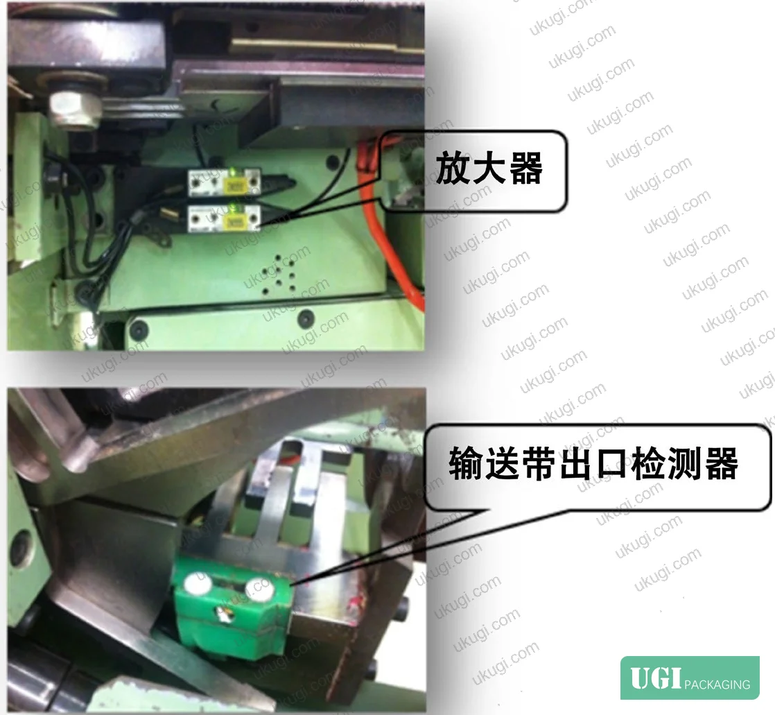
The compensation motor — a secondary drive element — monitors pack position via two optical detectors. Those detectors are active during a machine phase window of 239° to 259°. Within that window, the detectors check whether a pack is present at the conveyor exit. If no pack is detected during that phase interval, the compensation motor accelerates the internal gear mechanism. If a pack is detected early (before the window closes), the motor decelerates the mechanism. The target conveyor load is 68 to 70 packs in the belt channel, with 69 packs as the standard setpoint.
The internal gear speed-change mechanism operates as a fixed-axis gear train when the compensation motor is idle. When the compensation motor activates, the worm gear introduces a non-zero angular velocity (WH ≠ 0) and the system converts to a planetary differential gear train. Speed compensation is achieved by superimposing the worm gear rotation onto the gear shaft rotation: when WH and the gear shaft rotate in the same direction, the output decelerates; when they rotate in opposite directions, the output accelerates.
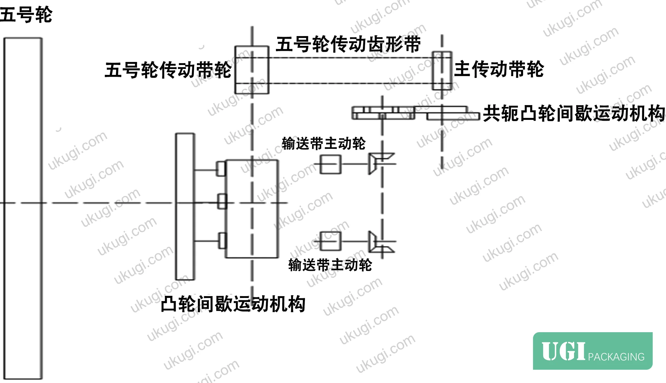
The conjugate cam intermittent mechanism drives the entire conveyor transmission chain. Its operating principle is precise: two cam profiles control a single follower simultaneously, with strictly alternating advance and retreat profiles. If the timing relationship between the two cam profiles is compromised — due to wear or incorrect phase adjustment — the mechanism either jams or delivers intermittent motion with increasing positional error.
Most procurement teams don’t realize that cam-roller clearance in conjugate mechanisms is a zero-tolerance specification. The design intent is zero clearance between cam and roller at all positions. The drive arc and the positioning arc engage the rollers symmetrically and uniformly — any deviation from this produces positioning error that accumulates per cycle. At 500 packs/min, even a small clearance growth translates to measurable pack position drift within minutes of operation.
Failure Modes and Their Impact on Packaging Quality #
Here is where the maintenance data gets directly relevant to packaging procurement decisions. Three distinct failure pathways were identified and documented:
Failure Mode 1: Compensation Motor Coupling Fracture
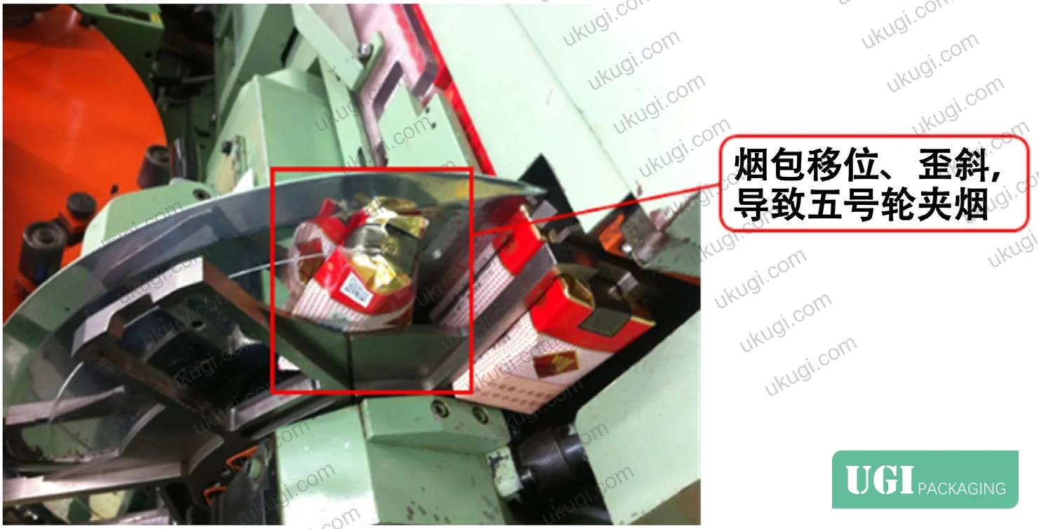
The coupling between the compensation motor and the worm gear mechanism is a consumable component under the dynamic load profile of the compensation cycle. When the coupling fractures, the compensation motor runs but delivers no torque to the internal gear mechanism. The result: the conveyor belt runs at fixed speed regardless of pack position, causing progressive phase drift. Packs arrive at the 5th wheel transfer station early or late, resulting in clamping faults. Diagnosis is straightforward — check whether the coupling rotates when the motor runs.
Failure Mode 2: Eccentric Seat Bearing Degradation
Inside the eccentric seat of the internal gear mechanism, a thin-profile bearing connects the gear shaft to the housing. This bearing is subjected to combined shock loading from the intermittent motion of the conjugate cam mechanism and the continuous tension load of the conveyor belt. It is the most wear-prone component in the assembly. When this bearing degrades, the gear shaft develops radial runout. The result is inconsistent gear mesh — audible as mechanism noise — and uneven conveyor belt motion. At advanced wear stages, gear tooth skipping occurs.
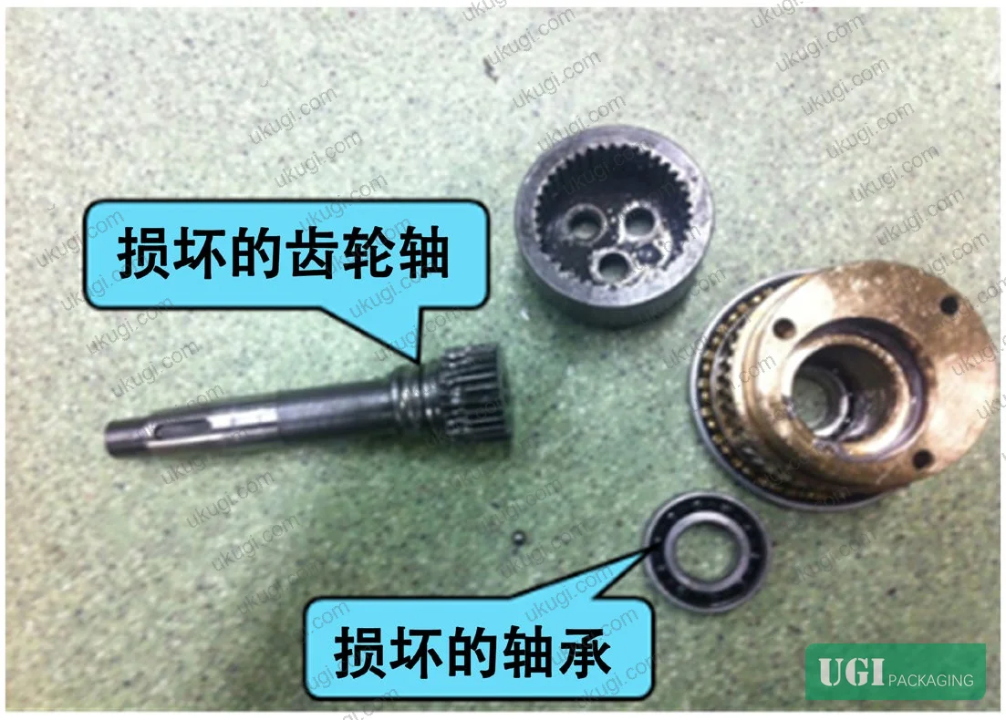
The worm gear support bearings at both ends of the worm shaft are subject to the same progressive wear mechanism. Ball wear increases radial clearance, which loosens the mesh between the internal gear and the gear shaft. When clearance becomes sufficient to allow tooth-skipping, pack clamping faults become continuous rather than intermittent.
Failure Mode 3: Conjugate Cam and Roller Surface Wear
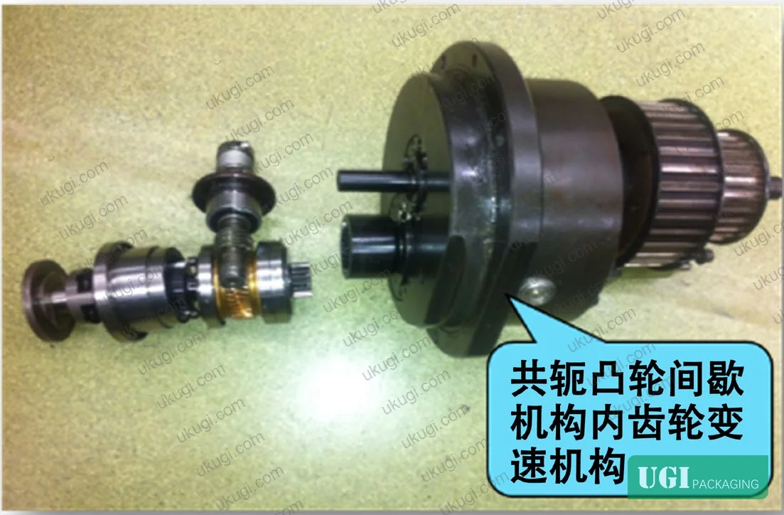
This is the most technically demanding failure to diagnose. The conjugate cam mechanism operates at high speed with inherent intermittent shock loading. The cam drive arc, positioning arc, and roller contact surfaces accumulate wear gradually. As the cam-roller clearance increases from zero, the mechanism loses positional precision. The critical progression is: clearance growth → increased impact loading per cycle → roller damage → roller axle pin fracture. Once the axle pin fractures, the roller cannot follow the cam profile and 5th wheel clamping faults become continuous.
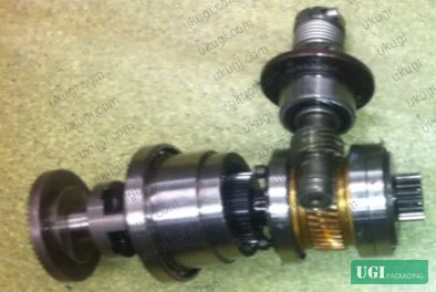
In supplier qualification work, tracking these failure modes across production equipment reveals a consistent pattern: three of the most common fault types in high-speed carton packaging all originate from the same root mechanism — progressive clearance growth in precision bearing and cam assemblies that are operating under combined shock and cyclic load. The equipment may appear to function normally for extended periods while clearance is accumulating, then fail suddenly when a threshold is crossed.
The pre-intervention fault frequency was 61.33 incidents per month. After replacing worn bearings, replacing the conjugate cam and roller assemblies, adjusting cam-roller clearance to zero, and recalibrating the compensation motor phase, fault frequency dropped to 13.33 incidents per month — a reduction of 78.3%. All three measurement months showed consistent improvement after the intervention.
Comparison of Operating Performance: Pre- and Post-Intervention #
| Metric | Pre-Intervention (Avg.) | Post-Intervention (Avg.) | Change |
|---|---|---|---|
| Pack shift + clamping fault frequency | 61.33 faults/month | 13.33 faults/month | −78.3% |
| Compensation motor phase window | Outside 239°–259° | Restored to 239°–259° | Phase corrected |
| Cam-roller clearance | Non-zero (worn) | Zero clearance achieved | Full reset |
| Conveyor belt pack count | Drifting from 69-pack setpoint | Stabilized at 68–70 packs | Within spec |
The magnitude of improvement — nearly 80% fault reduction — confirms that bearing and cam wear are the primary drivers, not secondary contributors. Honestly, most maintenance programs in packaging production environments treat bearing replacement as a reactive measure. The data here argues strongly for a preventive replacement schedule based on cycle count rather than waiting for audible symptoms.
Practical Guidance for Buyers #
If you are procuring high-volume folding cartons, rigid boxes, or tobacco-style packaging, the mechanical precision of your supplier’s packaging equipment is a direct determinant of finished product quality. Misregistration, inconsistent crease depth, corner deformation, and surface finish damage at the sealing station are all downstream effects of the kind of transmission drift documented in this analysis.
When evaluating a supplier’s production capability, ask specifically about their maintenance interval for conjugate cam mechanisms and compensation system calibration. A supplier who can answer with specific phase values (the 239°–259° window discussed here is a real production parameter), clearance specifications (zero-tolerance cam-roller mesh), and bearing replacement schedules demonstrates a fundamentally different level of process control than one who responds with generic quality assurance language.
For packaging that carries premium surface finishes — foil stamping, embossing, UV coating — the stakes are higher. These finishes are applied before the folding and forming stage, which means any positional drift in the packaging machine will produce visible defects on an already-finished surface. There is no downstream correction for a scuffed foil panel or a split embossed crease.
At ukugi.com, our team operates OEM/ODM packaging production for international brand owners across cosmetics, consumer goods, and premium retail — with full surface finishing capabilities and equipment maintained to the precision standards this analysis documents. If your project requires verified mechanical consistency at volume, we can walk you through our process controls before you commit to sampling.
For print and packaging dimensional tolerances relevant to high-precision carton production, ISO 12647-2:2013 Graphic technology — Process control for offset lithographic printing provides a useful baseline for registration and color consistency requirements. Structural integrity of the substrate itself is governed by standards such as ISO 2758:2014 Paper — Determination of bursting strength, which buyers should reference when specifying board grades for folding carton applications. For flexible packaging substrates used in combination packaging formats, ASTM D882 Standard Test Method for Tensile Properties of Thin Plastic Sheeting provides tensile performance benchmarks relevant to laminate selection.
Need a custom formulation or sample? Request a quote from our team →
Technical Verification Questions #
- What is the measured cam-roller clearance specification in your conjugate cam intermittent mechanism, and what is your maximum acceptable clearance before scheduled replacement? The design specification requires zero clearance — can you confirm your maintenance log shows clearance values at last service?
- What is the phase window range for your compensation motor detection system, and how frequently is motor phase recalibrated? The functional specification for this parameter is 239°–259° — deviation outside this range indicates compensation system drift.
- What is your current conveyor belt pack count setpoint, and what is the acceptable operational tolerance around that value? The standard operating range is 68–70 packs, with 69 as nominal — can you provide production data showing actual belt load stability over a 30-day period?
- What is your documented bearing replacement interval for eccentric seat bearings in the internal gear speed-change mechanism, and is that interval based on calendar time, production cycle count, or condition monitoring? This bearing is the highest-wear component in the transmission chain and its degradation is the primary cause of gear-mesh noise and pack positioning error.
- What was your pack shift and 5th wheel clamping fault frequency over the past three months, expressed as incidents per month? A well-maintained line at this equipment class should be running below 15 faults/month — the pre-intervention benchmark of 61.33 faults/month represents a degraded maintenance state.
Quality Verification Checklist #
- ☐ Compensation motor phase window confirmed within 239°–259° via machine phase meter at commissioning and after any motor replacement
- ☐ Conjugate cam-roller clearance verified at zero (no measurable gap) using feeler gauge, with support seat eccentricity adjustment documented
- ☐ Conveyor belt pack count confirmed at 68–70 packs (nominal 69) during production run verification
- ☐ Eccentric seat bearing replaced and radial runout measured below acceptable threshold; no audible gear-mesh noise during dry cycle
- ☐ Worm gear support bearings at both shaft ends replaced and mesh tightness confirmed — no tooth-skip detectable during manual rotation test
- ☐ Compensation motor coupling integrity confirmed — visual inspection and rotation check during live motor run
- ☐ Post-intervention fault frequency tracked over minimum 30-day period and confirmed below 15 incidents/month
Key Specifications Table #
| Parameter | Recommended Value | Verification Method |
|---|---|---|
| Compensation motor detection phase window | 239°–259° | Machine phase meter during live production cycle |
| Conveyor belt pack count (standard setpoint) | 69 packs (range: 68–70) | Physical count at belt exit during production |
| Conjugate cam-roller mesh clearance | Zero (0 mm) | Feeler gauge; eccentric support seat adjustment |
| Pack shift + clamping fault frequency | ≤15 incidents/month | Fault log review — 30-day rolling average |
| Compensation motor speed response | Phase-corrected within detection window | Motor phase calibration log; coupling rotation check |
Looking for a manufacturer that meets these specs? Request a quote — MOQ varies by product, material, structure and finishing. Product-specific MOQ is confirmed with each quotation.
References #
Data source: Fault Diagnosis and Mechanical Correction of Pack Shift and Transfer Clamping Failure in High-Speed Carton Packaging Machines, K.-P. Fang et al., Journal of Applied Polymer Science, 2024
Frequently Asked Questions #
What causes pack shift faults in high-speed carton packaging machines?
Pack shift originates from two primary mechanical sources: failure of the compensation mechanism (specifically the internal gear speed-change unit driven by the worm gear and compensation motor) and wear in the conjugate cam intermittent mechanism. When either system loses precision, the conveyor belt delivers packs outside the correct phase window for transfer, causing positional error at the output station.
How often should conjugate cam and roller assemblies be replaced?
There is no universal calendar interval — replacement should be triggered by measurable clearance growth, not just time in service. The design specification for conjugate cam-roller mesh is zero clearance. Once any measurable gap develops, the mechanism begins accumulating positional error per cycle. In practice, facilities running at 500 packs/min should implement cycle-count-based inspection rather than relying on audible symptoms, which typically appear only after significant wear has already occurred.
Does bearing wear in the eccentric seat always produce audible symptoms before it causes faults?
No — this is a common and costly assumption. Radial clearance in the eccentric seat bearing can develop to a level that causes inconsistent gear mesh and intermittent pack positioning errors well before any audible noise is detectable. The first observable symptom is often increased fault frequency, not mechanical noise. By the time gear-tooth skipping occurs (which is audible), the bearing has been in a degraded state for some time.
What is the significance of the 239°–259° phase window for the compensation system?
This phase window defines the operational envelope during which the pack position detectors are active and the compensation motor is permitted to respond. If the motor phase drifts outside this window — due to coupling wear, motor fault, or calibration drift — the compensation system either fails to respond to positioning errors or responds at the wrong point in the machine cycle, introducing rather than correcting positional error. Recalibrating motor phase to restore this window is one of the highest-impact single adjustments available in this system.
How do mechanical faults in packaging equipment affect printed surface quality on finished cartons?
Pack misalignment at the transfer station produces direct physical contact between the pack surface and the clamping mechanism at the wrong position. For cartons with premium surface finishes — foil stamping, UV coating, embossing — this contact scuffs or deforms the finish at a point where no corrective action is possible. For custom paper boxes or cosmetics packaging solutions carrying high-value surface treatments, mechanical precision in the forming and transfer stages is as important as the print specification itself.
Published by ukugi.com Technical Team | Request a quote


