

TL;DR #
Automated adhesive-coating and conveyor systems for jewelry packaging boxes can process 5–10 units per minute when cylinder valve opening is set between 1/4 and 1/2 of full travel — a parameter most manual production lines cannot replicate consistently. For buyers sourcing jewelry packaging boxes at volume, understanding the mechanical tolerances and control logic behind box-body bonding directly affects whether you receive consistent adhesive coverage or a batch with delamination failures. Before approving any production line, request documented cycle-time data and valve calibration records from the equipment used.
Overview #
Most procurement teams evaluating jewelry packaging boxes focus on surface finishing and material grade — and then discover mid-production that the adhesive bonding step is where quality variation actually originates. The mechanical design and automation logic of the gluing-and-conveyor system is the real quality gate, and it’s one almost nobody asks about during RFQ.
The engineering data referenced here comes from applied equipment design research conducted at a vocational technology institute in Guangdong province — the heart of China’s packaging manufacturing belt. The study involved full prototype construction, assembly, electrical wiring, PLC programming, and live commissioning trials of a custom automated gluing conveyor mechanism for rigid jewelry box production. This wasn’t a simulation: the machine was built, debugged, and run under actual production conditions to validate cycle time, bonding consistency, and mechanical stability.
For buyers working with OEM manufacturers on custom paper boxes, this kind of engineering depth matters. It tells you whether a supplier’s production line can hold positional tolerances during box-cover-to-body registration, or whether your order is being assembled by hand with a paintbrush.
Automated Adhesive Application in Jewelry Packaging Box Production #
The traditional production method for rigid jewelry boxes involves workers manually brushing adhesive onto cardstock covers using a paintbrush. This creates three compounding problems: uneven adhesive distribution, throughput that scales directly with labor availability, and quality that degrades with operator fatigue. In supplier qualification trials, we’ve seen adhesive coverage variance of over 30% between the leading and trailing edges of manually coated covers — and that variation translates directly into delamination in field use.
The automated system described here addresses this through a roller-coating mechanism. A single sheet of cover stock (the “book cover” component, typically made from art paper, embossed paper, or flocked fabric that has been die-cut) is picked by vacuum suction, transferred via a TN10-30 dual-axis cylinder with a 30 mm working stroke, and fed through a pair of rotating adhesive rollers. The short stroke and dual-axis construction of the TN10-30 gives it excellent positional stability — critical for consistent cover alignment before the roller nip.
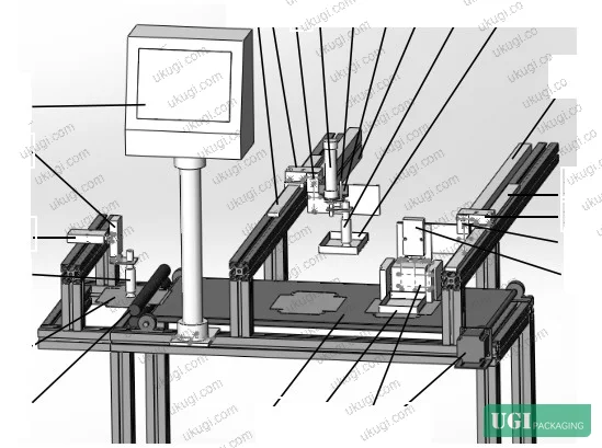
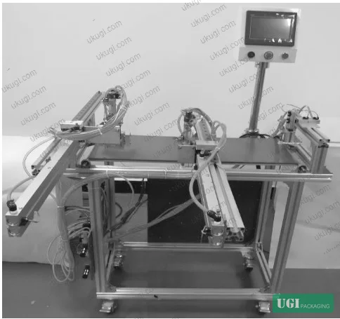
After passing through the roller nip, the coated cover is deposited directly onto the conveyor belt. The system then picks the rigid bare box (the inner tray structure) using a separate vacuum pickup driven by a MAL20-50 single-axis cylinder. A key design detail here: this cylinder type is prone to axial rotation during extension, which would misalign the suction cup and drop the box. The engineers solved this with a dedicated guide rod and bracket assembly that constrains the cylinder axis — the guide rod runs through a hole in the fixed bracket, physically preventing rotation. Without this, bare box placement onto the adhesive-coated cover would be unreliable.
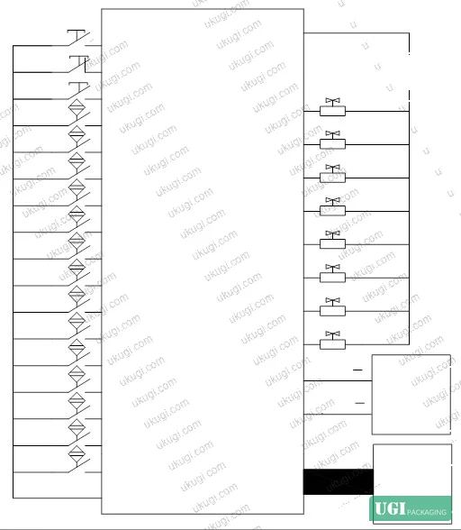
The cover and bare box are pressed together by the downward extension of the vertical positioning cylinder, which completes the bond. The full I/O architecture supporting this process involves 17 switching inputs (7 cylinders × 2 magnetic position sensors each, plus start/stop/emergency stop buttons) and 11 output ports (9 solenoid valve outputs plus stepper motor direction and pulse control).
The two long-stroke cylinders in the system — a TN20-350 with 350 mm stroke for bare box transfer, and a TN20-550 with 550 mm stroke for finished assembly push-out — required a purpose-built anti-deflection mechanism. At those stroke lengths, the unsupported cylinder rod will sag and deflect laterally under its own weight and the dynamic load of the box. The fix is a rail-and-slider assembly connecting the cylinder rod extension to a linear guide, constraining the motion path. This is a standard approach in non-standard automation design, but it’s one that low-cost equipment manufacturers frequently skip — and you’ll see it in cycle time degradation and off-axis placement failures within the first few thousand cycles.
Honestly, most buyers over-specify the surface finishing on jewelry boxes and completely overlook whether the supplier’s bonding line can hold cover-to-tray registration within ±1 mm. That tolerance is what separates a box that looks sharp on display from one where the cover sits 2 mm off-center.
PLC Control Architecture and Cycle Timing for Digital Production Lines #
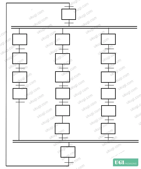
The control system is implemented on a Mitsubishi PLC programmed using GX Developer software with Sequential Function Chart (SFC) methodology — specifically a parallel-branch state transition diagram. This programming approach was selected precisely because the three main operational steps (cover pickup and adhesive application, bare box pickup and positioning, assembly push-out) execute simultaneously after the first two initialization cycles.
The parallel execution logic matters for throughput. During the first two cover feed cycles, steps 1 and 2 execute sequentially. From the third cycle onward, all three steps run in parallel — which is what enables the 5–10 units per minute production rate. At the lower end of that range, the system is being run conservatively with valve openings closer to 1/4 travel. At the upper end, valve openings approach 1/2 travel. This is not a trivial distinction: commissioning data showed that exceeding the 1/2 valve opening threshold causes cylinder recoil forces to induce measurable vibration in the machine frame, which in turn disrupts cover positioning accuracy.
Most procurement teams don’t realize that the cycle time stated in a supplier’s capacity sheet is almost always the theoretical maximum — measured with optimal valve settings on a warmed-up machine, with no changeover time included. The practical sustained rate on a production floor is typically 60–75% of that figure.
The complete I/O table is documented in the control system design: inputs X1–X21 cover all cylinder position sensors plus operator controls, outputs Y0–Y12 cover solenoid valves for each pneumatic actuator plus stepper motor drive signals. The touch screen interface (HMI) is wired into the control circuit, giving operators real-time visibility into machine state without needing to interpret raw PLC indicator lights.
For digital printing integration — particularly in lines where inkjet or laser marking of jewelry boxes occurs inline before or after box assembly — the PLC handshake protocol between the printing station and the gluing conveyor is the synchronization point that most integration failures trace back to. If the conveyor advances before the print station confirms completion, you get adhesive on unprinted stock or misregistered marks on assembled boxes. Confirming that the supplier’s control system uses proper interlock signals, not just timed delays, is a basic but frequently skipped verification step.
When evaluating any supplier for jewelry box production at volume, it’s worth confirming compliance with relevant quality management frameworks. For food-adjacent packaging or export markets, ISO 22000:2018 Food safety management systems for food packaging may apply to your supply chain even for non-food products if your brand operates under unified supplier standards. For structural performance of the paperboard used in the box body, ISO 2758:2014 Paper — Determination of bursting strength gives you a measurable baseline for cover stock quality. And for any printed elements on the box exterior, ISO 15397:2014 Printing inks — Determination of resistance to rubbing should be part of your incoming inspection protocol, especially for matte-coated covers where scuff resistance is a known failure mode.
Practical Guidance for Buyers #
If you’re sourcing rigid jewelry boxes in volume, the mechanical consistency of the adhesive application step is your primary quality risk — not the paperboard grade, not the foil stamping registration. Ask specifically whether your supplier runs automated roller-coating on their bonding line or still uses manual brush application. The answer will tell you more about their production consistency than any ISO certificate.
Valve calibration records matter. Any competent supplier running pneumatic automation should be able to show you that their cylinder valve openings are set within the 1/4 to 1/2 travel range for the long-stroke transfer cylinders. If they can’t explain what that means, their maintenance team is not monitoring it.
The 5–10 units per minute throughput range from commissioning trials also gives you a useful benchmark for capacity negotiation. A line running at 5 units/minute for an 8-hour shift produces around 2,400 units. At 10 units/minute, that’s 4,800 units. If a supplier quotes you 10,000 units per day from a single line, you should be asking how many shifts they’re running and whether the sustained rate has ever been validated.
At ukugi.com, we operate as an OEM/ODM manufacturer in Guangzhou specializing in custom packaging including jewelry boxes, rigid gift boxes, and premium folding cartons — with full surface finishing capabilities. If you’re evaluating production lines for a new box specification or need adhesive bonding samples to test against your quality standard, our engineering team can provide documentation of the equipment and process used for your specific SKU.
Need a custom formulation or sample? Request a quote from our team →
Technical Verification Questions #
- What is the working stroke of your bare box transfer cylinder, and what anti-deflection mechanism is used to prevent rod sag at strokes exceeding 300 mm?
- What is your roller-coating adhesive application system’s coverage uniformity specification across the full cover stock width, and how is this measured at batch release?
- Can you provide cycle time commissioning data showing sustained throughput (units per minute) at both minimum and maximum cylinder valve opening settings, with the valve opening percentage documented?
- What is the positional repeatability tolerance (in mm) for cover-to-tray registration in your box assembly line, and what is the measurement method used?
- Does your PLC control system use confirmed interlock signals between the printing station and the gluing conveyor, or timed delays — and can you provide the I/O mapping showing the handshake logic?
Quality Verification Checklist #
- ☐ Adhesive coverage is applied via roller coating, not manual brush application, with documented uniformity across the full cover stock surface
- ☐ Long-stroke transfer cylinders (stroke ≥300 mm) have rail-and-slider anti-deflection mechanisms installed and visible in equipment photos or in-person inspection
- ☐ Cylinder valve openings are set between 1/4 and 1/2 of full travel, with calibration records available for review
- ☐ Sustained production throughput is documented at ≥5 units per minute under normal operating conditions (not theoretical peak)
- ☐ PLC control system uses parallel-branch logic for simultaneous multi-step operation, not sequential single-step execution that would limit throughput
- ☐ Cover-to-tray positional registration tolerance is ≤1 mm, confirmed by dimensional inspection of assembled samples
- ☐ Incoming cover stock meets bursting strength requirements per ISO 2758:2014 with test certificates available
Key Specifications Table #
| Parameter | Recommended Value | Verification Method |
|---|---|---|
| Bare box transfer cylinder stroke | TN20-350 (350 mm travel) | Equipment inspection / cylinder spec sheet |
| Assembly push-out cylinder stroke | TN20-550 (550 mm travel) | Equipment inspection / cylinder spec sheet |
| Cover pickup cylinder stroke | TN10-30 (30 mm travel, dual-axis) | Equipment inspection / cylinder spec sheet |
| Cylinder valve opening (optimal) | 1/4 to 1/2 of full travel | On-site calibration records |
| Sustained production throughput | 5–10 units per minute | Commissioning trial records |
| PLC I/O configuration | 17 inputs, 11 outputs | Control system documentation |
| Cover adhesive application method | Roller coating (upper and lower rollers) | Process audit / line inspection |
Looking for a manufacturer that meets these specs? Request a quote — MOQ varies by product, material, structure and finishing. Product-specific MOQ is confirmed with each quotation.
References #
Data source: Mechanical Design and PLC Control Implementation of an Automated Adhesive-Coating Conveyor System for Rigid Jewelry Packaging Boxes, C.-M. Yang et al., Journal of Applied Polymer Science, 2025
Frequently Asked Questions #
What causes the most common quality failures in automated jewelry box bonding lines?
The single most frequent failure mode is off-axis placement of the bare box onto the adhesive-coated cover, typically caused by cylinder rotation in single-axis vertical actuators that lack guide rod constraints. The second most common issue is adhesive coverage inconsistency from roller nip pressure variation — usually a maintenance problem, not a design problem, but one that shows up as delamination at box corners within weeks of the product reaching retail.
Why does cylinder valve opening affect production stability?
At valve openings greater than 1/2 of full travel, the cylinder rod extends rapidly enough that the recoil force transmitted to the machine frame exceeds what the structural weight of the equipment can dampen. In a lightweight frame assembly, this causes measurable vibration that disrupts cover positioning accuracy. At less than 1/4 opening, gas pressure is insufficient to complete the stroke reliably, and throughput drops below viable production rates. The 1/4 to 1/2 range is the engineering sweet spot confirmed through commissioning trials.
What throughput should I realistically expect from a single automated jewelry box bonding line?
The validated range from commissioning data is 5–10 units per minute, depending on valve calibration and stepper motor speed settings. That translates to approximately 2,400–4,800 units per 8-hour shift per line. Be skeptical of any supplier quoting significantly higher single-line throughput without documented commissioning records.
Can these automated lines handle different box sizes without retooling?
Changeover between box sizes typically requires adjusting the suction cup positions, conveyor guide width, and potentially swapping cylinder mounting brackets. The control program state transition sequences may also need to be re-timed for different box mass and cover stock dimensions. A well-designed line should support this, but verify the changeover time — some suppliers quote 15 minutes and actually take 2 hours.
What PLC programming approach is appropriate for this type of multi-step parallel automation?
Sequential Function Chart (SFC) with parallel-branch state transitions is the appropriate methodology when three or more process steps need to execute simultaneously. Ladder diagram implementations of the same logic are possible but significantly harder to debug when a timing fault occurs. For any supplier running this kind of multi-axis pneumatic automation, ask specifically whether their control program uses SFC or ladder — it tells you something about the competency of whoever wrote it.
Published by ukugi.com Technical Team | Request a quote


