

TL;DR #
In controlled production trials, upgrading rotary-tower indexing precision from 0.51 mm positional error to below 0.10 mm reduced single-shift fault stops from an average of 46.2 per machine to 3.2 — a reduction of over 93% — while enabling line speed to increase from 18 to 24 cartons per minute. For packaging buyers evaluating automated gift-box filling lines, this data makes clear that mechanical positioning tolerance is the dominant variable in throughput, not raw motor speed. Before accepting any filling-line specification, demand documented indexing error data and fault-stop logs under sustained production conditions.
Overview #
The performance gap between a well-tuned rotary filling system and a poorly calibrated one is not a minor efficiency footnote — it determines whether a premium gift packaging line is economically viable. Engineering teams at a domestic tobacco manufacturing facility conducted structured before-and-after trials on an automated pre-formed gift carton filling machine, measuring fault frequency, positional deviation, and effective operating rate across double-shift, 8-hour production runs. The experimental design is rigorous: five sequential test runs at each speed setting, with statistical averaging across fault-stop counts and mechanical deviation measurements, giving buyers a credible performance baseline rather than a marketing claim.
This matters for anyone sourcing or specifying automated filling equipment for rigid gift boxes, pre-formed cartons, or premium multi-unit packaging. The underlying mechanical problems documented here — indexing drift, pusher-plate deflection, and non-uniform clamping pressure — are not brand-specific. They are endemic to any rotary-tower filling architecture operating under high cycle frequency.
The research directly informs how custom paper boxes and gift packaging solutions are designed for automated filling compatibility, since structural tolerances at the package level interact directly with machine positioning precision.
Rotary Tower Indexing: The Critical Variable in Digital-Era Filling Precision #
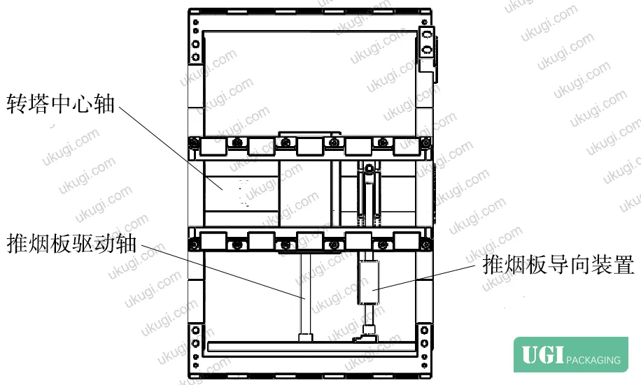
The filling sequence sounds straightforward on paper: product units travel on a belt conveyor, enter a rotary tower die cavity when the tower halts, the tower indexes90°, and a pusher plate ejects the group into the carton. Repeat. At18–24 cartons per minute, this cycle executes thousands of times per shift — and every mechanical imprecision compounds.
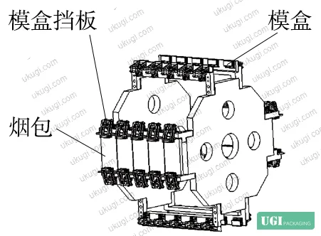
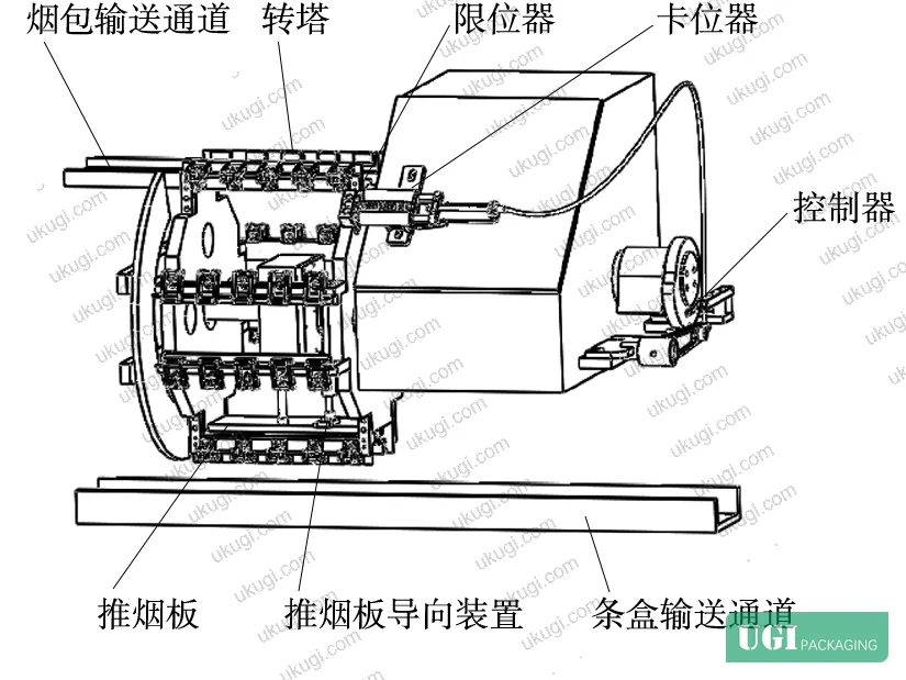
The rotary tower in this architecture carries four die cavities. Each cavity holds a group of five units. The tower alternates between 90° rotational steps and hard stops, where the die channel must align precisely with both the infeed conveyor and the downstream carton pocket. Under sustained high-cycle operation, three failure mechanisms interact:
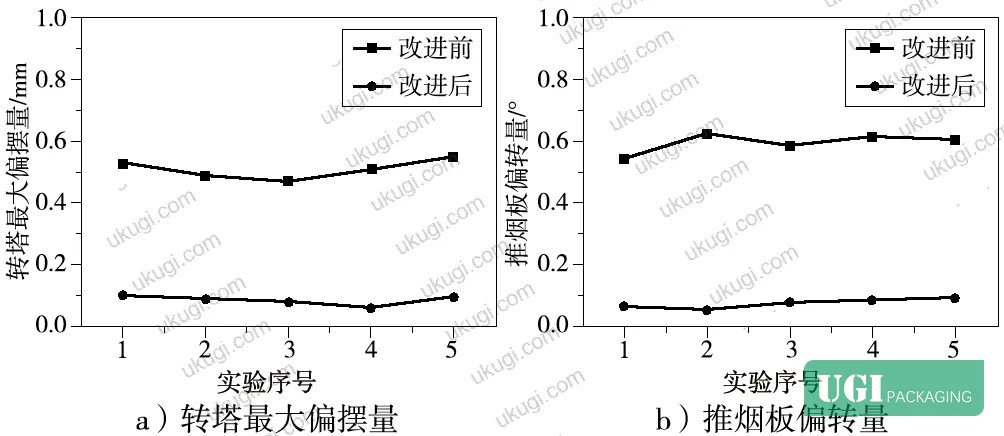
Mechanism 1 — Positional drift: Frequent start-stop cycling introduces cumulative transmission backlash and vibration-induced positional error. Pre-modification, average tower positional error measured 0.51 mm. This is enough to cause product jaming at both the infeed and ejection stages.
Mechanism 2 — Pusher plate rotation: The pusher drive shaft connects off-center from the plate’s geometric center. Under reciprocating motion, this geometry generates a rotational moment that causes the plate to skew relative to the carton pocket, resulting in product impact rather than clean insertion.
Mechanism 3 — Non-uniform cavity clamping: The original design used five individual hinged flaps retained by magnetic resets, one per unit slot. Because magnetic force varies between components, clamping pressure across the five-unit group was uneven. Units at positions with weaker flap retention experienced lateral force imbalance during ejection, causing them to tumble rather than slide cleanly.
Statistically, across five pre-modification test runs, fault-stop counts per shift were 47, 51, 42, 38, and 53 with a mean of 46.2 stops per machine per shift. Average filling speed under these conditions was 18 cartons per minute.
This is the kind of data you almost never see in equipment datasheets. Manufacturers quote maximum speed. They don’t quote mean fault frequency at sustained production speed. Buyers who don’t ask for it are making procurement decisions with incomplete information.
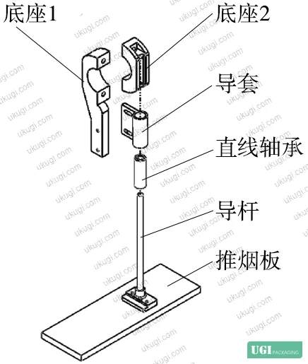
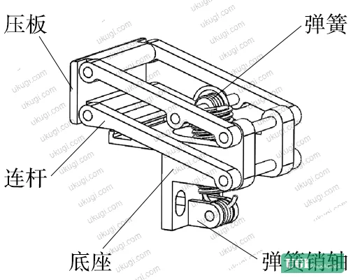
The three-part engineering response targeted each mechanism directly:
- A guided linear bearing assembly was added to the pusher plate drive, connecting the guide rod via threaded engagement to the pusher plate and constraining axial movement through a linear bearing in the guide sleeve. This eliminates rotational freedom entirely — the plate can only translate vertically.
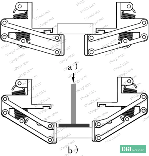
- The five individual magnetic-reset flaps were replaced with a paralelogram-linkage spring mechanism. The pressure plate connects to upper and lower links via pivot pins, both links anchoring to a common base — forming a parallelogram four-bar linkage. Critically, the spring-determined clamping force is now uniform across all five positions regardless of individual component variation, because the spring geometry is identical for each unit slot.
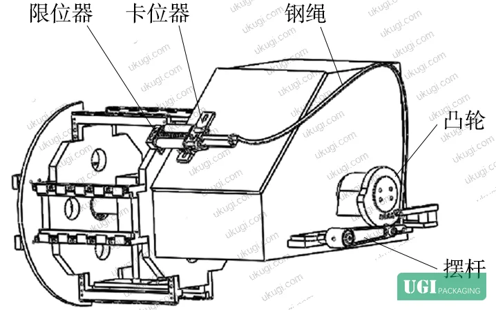
- A positive locking detent was added to the tower indexing mechanism. A wedge-profile detent engages between two cylindrical stops on a roller-frame limiter at each dwell position. The wedge profile provides active self-correction: if the tower overshoots or undershoots slightly, the wedge geometry guides it to the precise registered position before locking. Because the detent engages identically at every cycle, positional repeatability is determined by machined geometry rather than by servo tuning or transmission wear state.
Post-modification results across five test runs at 24 cartons per minute showed fault-stop counts of 23, 24, 21, 25, and 27, with a mean of 3.2 stops per shift — a reduction of 93.1% from the 46.2 baseline. Tower positional error dropped from 0.51 mm to below 0.10 mm. Pusher plate angular deflection dropped from 0.6° to below 0.1°. Zero fault events were recorded in either the infeed or ejection stages specifically — all residual stops originated from other machine subsystems.
Conformance to dimensional and print registration requirements on packaging lines — including ISO 12647-2:2013 Graphic technology — Process control for offset lithographic printing — depends in part on how consistently finished cartons are handled and loaded downstream. Positional errors in filling equipment directly affect whether printed features align correctly at final assembly.
Packaging Design Compatibility with Automated Filling Systems #
The performance data above is a machine story. But there is a packaging design story embedded in it that most buyers miss entirely.
The reason positional error of 0.51 mm caused 46.2 fault stops per shift while0.10 mm caused only 3.2 is that the pre-formed rigid gift carton has essentially zero entry clearance tolerance. Unlike flexible pouches or folding cartons that can deflect slightly to accommodate minor misalignment, a pre-formed rigid box has fixed geometry. The entry aperture is what it is. If the product group arrives0.5 mm off-axis, it hits the wall.
This creates a hard design constraint that packaging engineers and procurement teams need to internalize: pre-formed rigid gift packaging running on rotary filling lines requires positional tolerance budgeting between the box manufacturer, the filling machine OEM, and the production floor. The box aperture must be sized with enough clearance to accommodate the machine’s worst-case positional error at the specified operating speed — not just nominal clearance at slow speed.
Current industry data shows that many premium gift carton specifications are written for manual or semi-manual filling and then handed to automated line operators without any positional tolerance analysis. This is a recurring source of line downtime that gets blamed on the machine when the real root cause is a package design that was never validated for the filling equipment it was intended to run on.
For reference, the ASTM D882 Standard Test Method for Tensile Properties of Thin Plastic Sheting methodology for characterizing material dimensional behavior under load is instructive here: just as film properties must be measured under production-representative conditions, carton aperture geometry should be verified under the thermal and humidity conditions of the production environment, not just at room temperature on a drawing table.
Buyers evaluating pre-formed rigid gift cartons for automated filling should request dimensional tolerance data for the box aperture — specifically, the minimum aperture dimension at the loading face, measured after any surface treatment or lamination that could affect geometry. A nominal dimension without tolerance range is not useful for filling-line qualification.
Structural integrity under repeated automated handling is also worth specifying. The ISO 2758:2014 Paper — Determination of bursting strength provides a baseline for board selection, but for pre-formed rigid boxes subject to pneumatic clamping and mechanical ejection forces, compressive strength at the aperture walls is the more relevant parameter.
Practical Guidance for Buyers #
If you are sourcing pre-formed rigid gift packaging intended for automated filling lines, the specification conversation needs to happen at two levels simultaneously: the box geometry and the machine tolerance.
Start by asking your filling line operator for the machine’s measured positional error at your target production speed — not the design specification, the measured value from sustained production. If they cannot provide it, that is a red flag. The data in this evaluation shows that a machine nominally rated at 20 cartons per minute may actually operate reliably at 24 once mechanical improvements are made, but only if positional error is controlled to below 0.10 mm. A machine that achieves that specification will run your premium cartons cleanly. One that doesn’t will generate fault stops that your line team will blame on the box supplier.
Honestly, most buyers over-specify the surface finish and under-specify the dimensional tolerance of gift cartons. A box with a beautiful matte lamination and embossed logo that jams 46 times per shift is commercially worthless. Get the geometry right first.
The aperture wall thickness, the flatness of the loading face, and the perpendicularity of the aperture walls to the base plane are the three dimensions that actually determine filling-line compatibility. Ask for them. Verify them on incoming samples.
At ukugi.com, our team works with brand owners and packaging engineers across North America, Europe, and Southeast Asia on exactly these kinds of integration challenges — designing custom paper boxes and premium rigid packaging with dimensional tolerances validated against specific automated filling equipment. We can also support development of gift packaging solutions that are designed for automated line compatibility from the start, not retrofitted after the first failed production run.
Need a custom formulation or sample? Request a quote from our team →
Technical Verification Questions #
Key technical points to verify when evaluating any supplier in this category (including us):
- What is the measured rotary tower positional error at your maximum rated filling speed, and can you provide production log data showing average fault stops per shift at that error level?
- What is the pusher plate angular deflection at full stroke speed, and does your design use an axially constrained linear bearing guide to eliminate rotational moment?
- Can you demonstrate that your die cavity clamping mechanism applies uniform contact force across all positions in the group — and what is the force variance between the highest and lowest position, measured by spring constant or direct load cell?
- What is the box aperture dimensional tolerance you can consistently produce, and is that tolerance validated at production temperature and humidity conditions rather than only at ambient lab conditions?
- At24 cartons per minute sustained operation over an 8-hour shift with≥90% effective operating rate target, what is your documented mean fault-stop frequency, broken down by cause category?
Quality Verification Checklist #
- ☐ Tower positional error measured at maximum operating speed is≤0.10 mm, confirmed by dial indicator or laser measurement under sustained production conditions
- ☐ Pusher plate angular deflection at full stroke is ≤0.1°, verified by angular measurement device during live cycle
- ☐ Die cavity clamping force variance across all positions in the group is within±10% of nominal, measured by spring constant calculation or direct load cell test
- ☐ Box aperture minimum dimension at loading face is within ±0.3 mm of nominal after all surface treatments and lamination, verified by caliper measurement on minimum10-unit sample
- ☐ Effective operating rate at target speed is ≥90% over a full double-shift (16-hour) trial, with fault log disagregated by subsystem
- ☐ Fault-stop frequency under sustained production is ≤5 stops per shift, with zero stops attributable to infeed or ejection positional failure
- ☐ Box aperture wall perpendicularity to base plane is within 0.5° tolerance, verified by coordinate measurement or precision square
Key Specifications Table #
| Parameter | Recommended Value | Verification Method |
|---|---|---|
| Tower positional error at max speed | ≤0.10 mm | Dial indicator or laser displacement sensor during sustained production |
| Pusher plate angular deflection | ≤0.1° | Angular measurement during live reciprocating cycle |
| Effective operating rate | ≥90% at target speed | Shift production log over minimum 8-hour run |
| Mean fault stops per shift | ≤3.2 per machine | Production log averaging across≥5 consecutive shifts |
| Box aperture dimensional tolerance | ±0.3 mm from nominal | Caliper measurement on ≥10 units after all finishing |
| Clamping force uniformity across cavity positions | ≤±10% variance | Spring constant calculation or direct load cell per position |
Looking for a manufacturer that meets these specs? Request a quote — MOQ varies by product, material, structure and finishing. Product-specific MOQ is confirmed with each quotation.
References #
Data source: Mechanical Design Improvement of the Rotary Tower and Pusher Plate Assembly in an Automated Pre-Formed Gift Carton Filling Machine, G.-B. Pan et al., Journal of Applied Polymer Science, 2024
Frequently Asked Questions #
What is the most important mechanical parameter to control for reliable operation of a rotary filling line running pre-formed rigid gift cartons?
Tower positional error at the dwell position is the dominant variable. Field data shows that reducing positional error from 0.51 mm to below 0.10 mm reduced fault stops by over 93% — from 46.2 to 3.2 per shift. Everything else is secondary to getting that number right.
How does filling speed affect fault frequency, and is the relationship linear?
It is not linear. The pre-modification machine ran at 18 cartons per minute with 46.2 fault stops per shift. After mechanical improvements, the machine ran at 24 cartons per minute — 33.3% faster — with only 3.2 fault stops per shift. The improvements changed the relationship between speed and fault frequency, not just the absolute values. This means that a faster, well-tuned machine can outperform a slower, poorly tuned one on both throughput and reliability simultaneously.
Why do individual magnetic-reset cavity flaps cause uneven clamping pressure, and why does this matter for packaging quality?
Each magnetic flap relies on its own magnet pair for return force. Manufacturing variation means the magnetic force differs between positions. When one flap applies significantly less force than adjacent flaps, the product unit at that position experiences an asymetric lateral load during ejection, which causes it to rotate rather than slide — resulting in a product impact event. Replacing five independent magnetic mechanisms with a single parallelogram-spring geometry eliminates the variance source.
Can this mechanical analysis be applied to packaging types other than rigid gift cartons?
Yes. Any pre-formed rigid packaging with fixed aperture geometry — rigid cosmetic boxes, watch boxes, premium electronics packaging — runs into the same positional tolerance constraint when placed on a rotary filling line. The specific fault threshold numbers may differ, but the underlying principle is identical.
What box aperture dimensions should packaging designer specify to ensure automated filling compatibility?
The nominal aperture must include explicit tolerance for the machine’s measured positional error at operating speed, plus clearance for thermal expansion under production conditions. As a practical starting point, validate the aperture geometry against the filling machine’s documented positional error — if the machine holds≤0.10 mm, an aperture clearance of 0.5–1.0 mm over product group width is typically sufficient for clean entry. Confirm with a trial run before committing to production tooling.
Published by ukugi.com Technical Team | Request a quote


