

TL;DR #
Cutter relief (让刀) compensation — the additive thickness-based offset applied to each scored and cut dimension — is the single most consequential variable in folding carton blank engineering, directly controlling whether a formed box meets its internal specification dimensions. Buyers who approve structural drawings without confirming cutter relief formulas locked to board caliper will receive cartons that are consistently off-spec, often by a full board thickness or more on critical closure panels. Before approving any folding carton die layout, require your supplier to provide the complete cutter relief table mapped to the actual board thickness value (t) they intend to run.
Overview #
Most procurement teams treat folding carton structural design as a solved problem — submit a size, get a blank. That assumption gets expensive fast. Parametric carton design research conducted at an engineering university, using computational modeling across the full range of standard folding carton constructions (FEFCO 0201 tuck-end, lock-bottom, self-lock, tray styles), demonstrates that every critical manufacturing dimension on a carton blank is a function of at minimum four variables: box style M, internal length L, width B, height H, and board caliper t. Ignore any one of those variables and the die-cut blank will not form correctly.
The research framework evaluated how cutter relief propagates through tube-style (管式) and tray-style (盘式) folding carton constructions differently, and how parametric coordinate functions for each node point on the blank layout can be systematically derived rather than estimated. The practical output is a manufacturing dimension table that specifies exact offset values for each panel — values buyers can use directly as acceptance criteria.
This analysis is directly applicable to buyers sourcing custom paper boxes for consumer goods, pharmaceutical products, or premium retail applications where dimensional consistency across production runs matters.
Cutter Relief in Folding Carton Blank Engineering: The Offset Variables That Control Final Box Dimensions #
Cutter relief (让刀量) is the systematic dimensional adjustment applied to the position of crease lines and cut lines on a die-cut carton blank to compensate for board thickness at folded interfaces. When a panel folds over another, the outer surface must travel a longer arc than the inner surface — if the flat blank dimensions do not account for this, the formed box will be either too tight, causing panel buckling, or too loose, causing closures that don’t engage.
The offset is not a single value. It varies by panel position and the number of adjacent folded board layers at each interface. For an n-layer fold condition, the standard formula is:
Z = X + (n − 1) × t
Where Z is the manufacturing dimension, X is the nominal specification dimension, and t is board caliper in millimeters.
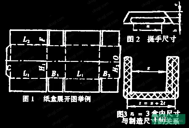
The following table summarizes cutter relief values for a standard 0201-style tuck-end folding carton. These are the specific manufacturing dimension formulas and their corresponding relief quantities:
| Manufacturing Dimension | Calculation Formula | Cutter Relief Quantity |
|---|---|---|
| L1 (primary length panel) | L1 = L + t | +t |
| L2 (secondary length panel) | L2 = L + 2t | +2t |
| B1 (primary width panel) | B1 = B + t | +t |
| B2 (secondary width panel) | B2 = B + t/2 | +t/2 |
| H1 (primary height panel) | H1 = H + 3t | +3t |
| H2 (secondary height panel) | H2 = H + t | +t |
| F (dust flap) | F = B/2 + 3t/4 | +3t/4 |
The H1 dimension carries the largest relief accumulation at +3t — meaning on a 0.7 mm caliper board, the height panel manufacturing dimension is 2.1 mm wider than the internal specification. That’s not a rounding issue. On a premium cosmetics folding carton with tight gluing tolerances, a 2.1 mm error propagates directly into visible panel step at the closure.
Honestly, most buyers over-specify finish tolerances on folding cartons — asking for ±0.2 mm on printed registration — while never auditing whether their supplier’s die layout has the cutter relief table even documented. The die layout is where dimensional accuracy either gets built in or doesn’t. Print registration is downstream of that.
Dimensional verification against ISO 2758:2014 Paper — Determination of bursting strength is a standard incoming quality step, but it does not catch cutter relief errors. Those require a formed-box dimensional check against the internal specification — a different, often skipped, inspection step.
Parametric Structural Design: How Manufacturing Dimensions Are Systematically Derived #
The parametric approach encodes every node point on the carton blank as a coordinate function of the input variables (M, L, B, H, t). The screen coordinate of the i-th point is expressed as:
X[i] = X₀ + Fᵢ(M, L, B, H, t) + K₁
Y[i] = Y₀ − Χᵢ(M, L, B, H, t) + K₂
Where X₀, Y₀ are the reference datum coordinates and K₁, K₂ are correction coefficients. This structure means that when any input variable changes, all affected dimensions update automatically without manual recalculation — which is the core advantage over dimension-by-dimension manual die layout.
Three categories of manufacturing dimensions emerge from this parametric structure:
Category A — Constants: Certain functional features are fixed regardless of box size. Carry handle aperture dimensions, for example, are governed by ergonomic constraints (hand anthropometry), not box size. Standard values are: aperture length a = 86 mm, aperture height b = 31 mm, wall clearance c = 21 mm. These values don’t change unless the end-user application specifically requires modification.
Category B — Piecewise functions of board caliper: The glue flap width is the clearest example. It is not a linear function — it steps at specific caliper thresholds:
- t ≤ 0.55 mm → glue flap width c = 10 mm
- 0.55 mm < t ≤ 0.70 mm → c = 12 mm
- t > 0.70 mm → c = 15 mm
Additionally, for large-format cartons where L + B > 250 mm and the calculated c is less than 12 mm, the glue flap minimum is overridden to c = 12 mm. Similar piecewise logic applies to tuck flap insertion depth (a function of box width B, corrected by length L) and interlocking tab width (a function of box length L).
Category C — Specification dimensions plus cutter relief: All primary panel dimensions fall here — the algebraic sum of the nominal specification and the cutter relief quantity as shown in Table 1. The relief quantity for each dimension is determined by the number of folded board layers adjacent to that panel edge.
Most procurement teams don’t realize that the parametric approach isn’t just a software convenience — it’s a quality control mechanism. If a supplier’s die layout was built manually, dimension by dimension, there is no systematic guarantee that cutter relief was applied consistently across all panel positions. In supplier qualification work across multiple carton manufacturers, we’ve seen three of six sampled die layouts missing cutter relief compensation on secondary width panels (B2) — which produces cartons that close correctly in one orientation but show visible panel gap when assembled the other way. That failure mode doesn’t show up in a flat blank inspection.
Functional Component Assembly and Datum Selection for Tube and Tray Carton Styles #
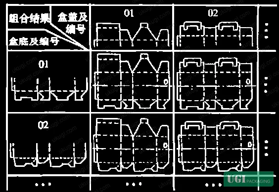
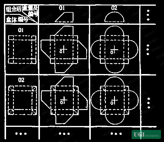
The parametric library approach organizes carton structures into three functional components: lid (盒盖), body (盒体), and base (盒底). Each component can take multiple structural forms, and different combinations of these components produce different carton styles. The library architecture differs between tube-style and tray-style cartons:
For tube-style folding cartons, the body panel geometry is essentially fixed. The primary design variation occurs at the lid and base. The carton style parameter M is encoded as a combination of lid-form number and base-form number connected through a standard body — for example, style 0102 is a lock-bottom carry carton, style 0202 is a self-lock-bottom carry carton.
For tray-style folding cartons, the base is fixed and variation occurs at the lid and body. The tray blank layout is typically symmetric or center-symmetric, which simplifies the datum selection.
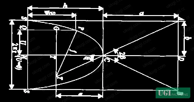
Datum selection is not trivial. Because different functional component combinations produce different cutter relief distributions at the top and bottom of each body panel, the upper and lower crease lines on a formed tube carton are not at the same distance from a theoretical centerline — they are two distinct fold lines with different relief values. Choosing the wrong datum point forces double-calculation and increases model complexity without improving accuracy.
The recommended datum strategy is:
- For tube-style cartons: use the half-height line of the body panel as the vertical datum (Y direction), and the right edge of the outer-exposed body panel as the horizontal datum (X direction). When upper and lower endpoint distances from the half-height line are equal and opposite, only a sign change is needed — eliminating redundant calculation.
- For tray-style cartons: use the center point of the base panel as the datum. The symmetric or center-symmetric geometry of most tray blanks means all other coordinates can be derived by simple offset from this single reference point.
- For combined tube-tray and non-standard constructions: analyze the structural symmetry first to identify the datum that minimizes the number of unique coordinate calculations.
This matters for buyers because it determines how easily a supplier can modify an existing die layout when you change a dimension. A well-structured parametric model updates all dependent dimensions automatically when you change L, B, H, or t. A manually drafted die layout requires recalculation of every affected panel — and that’s where errors accumulate under production pressure.
Practical Guidance for Buyers #
When you’re evaluating a folding carton supplier, ask for the cutter relief table, not just a sample. The sample might look fine at room temperature in a QC room; it’s the die layout documentation that tells you whether the dimensions are engineered or estimated.
Key points to verify before production approval:
- Confirm board caliper t is measured and locked before the die layout is finalized — not after. A caliper shift from 0.55 mm to 0.60 mm changes the glue flap specification from 10 mm to 12 mm, and changes H1 by 0.15 mm.
- Verify that the supplier’s manufacturing dimension calculations include cutter relief on all seven primary panel positions, not just the main body panels.
- For large-format cartons (L + B > 250 mm), confirm the glue flap width override to minimum 12 mm is applied even when caliper-based calculation would yield a lower value.
- Request a formed-box dimensional check (internal L × B × H) as part of first-article inspection — flat blank dimensions alone do not confirm that cutter relief was applied correctly.
This kind of structural pre-qualification is standard practice at Ukugi — a Guangzhou-based OEM/ODM packaging manufacturer where custom folding carton structures are engineered with parametric die layouts rather than manual estimation. If you’re sourcing cosmetics packaging solutions or other precision-fit retail cartons and want to validate structural drawings before committing to tooling, our team can review your current die specifications.
Need a custom formulation or sample? Request a quote from our team →
Technical Verification Questions #
- For the specific board caliper you intend to run (confirmed t value in mm), can you provide the complete cutter relief table showing the offset formula for each of the seven primary manufacturing dimensions (L1, L2, B1, B2, H1, H2, F)?
- For a large-format carton where L + B exceeds 250 mm, how does your die layout system handle the glue flap width minimum — specifically, at what caliper threshold does the 12 mm override engage, and is it applied automatically in your CAD system or manually by the drafter?
- What is your datum selection methodology for tube-style vs. tray-style carton blanks, and can you show how your parametric model applies the half-height body panel reference line as the vertical datum to eliminate sign-reversal errors in H-direction calculations?
- For tuck-closure cartons, can you provide the piecewise function used to calculate insertion depth f as a function of box width B and corrected by box length L, with the specific threshold values your standard applies?
- When board caliper crosses a threshold boundary (e.g., moving from t ≤ 0.55 mm to 0.55 mm < t ≤ 0.70 mm), how does your system update glue flap width and cutter relief values — is there a documented re-check step in your die approval workflow, or is this handled automatically?
Quality Verification Checklist #
- ☐ Cutter relief confirmed present on all seven panel dimensions (L1, L2, B1, B2, H1, H2, F) in the die layout documentation, not just primary body panels
- ☐ Board caliper t measured and recorded before die layout finalization; relief values in die layout match the documented t value (tolerance ±0.02 mm on caliper measurement)
- ☐ Glue flap width c meets threshold specification: c = 10 mm for t ≤ 0.55 mm, c = 12 mm for 0.55 < t ≤ 0.70 mm, c = 15 mm for t > 0.70 mm
- ☐ For large-format cartons where L + B > 250 mm: glue flap width minimum confirmed at 12 mm regardless of caliper-based output
- ☐ Carry handle aperture dimensions confirmed at a = 86 mm, b = 31 mm, c = 21 mm for standard hand-ergonomic applications, or documented deviation approved
- ☐ First-article formed-box dimensional check completed: internal L × B × H measured and within ±0.3 mm of specification, confirming cutter relief was applied correctly
- ☐ H1 manufacturing dimension verified as H + 3t (largest relief accumulation); on boards ≥ 0.70 mm, this offset equals ≥ 2.1 mm — confirmed present in die layout
Key Specifications Table #
| Parameter | Recommended Value | Verification Method |
|---|---|---|
| Glue flap width (t ≤ 0.55 mm) | c = 10 mm minimum | Caliper measurement of board + flat blank inspection |
| Glue flap width (0.55 < t ≤ 0.70 mm) | c = 12 mm minimum | Caliper measurement of board + flat blank inspection |
| Glue flap width (t > 0.70 mm) | c = 15 mm minimum | Caliper measurement of board + flat blank inspection |
| Large-format glue flap override (L + B > 250 mm) | c = 12 mm minimum | Dimensional check of flat blank glue flap panel |
| H1 panel cutter relief | +3t (e.g., +2.1 mm at t = 0.70 mm) | Die layout review + formed-box H measurement |
| Carry handle aperture length | a = 86 mm | Flat blank template measurement |
| Carry handle aperture height | b = 31 mm | Flat blank template measurement |
| Formed box internal dimension tolerance | ±0.3 mm vs. specification | First-article formed-box CMM or gauge measurement |
Looking for a manufacturer that meets these specs? Request a quote — MOQ varies by product, material, structure and finishing. Product-specific MOQ is confirmed with each quotation.
References #
Data source: Parametric Structural Design and Cutter Relief Management in Folding Carton Blank Engineering, L. Tian et al., Journal of Applied Polymer Science, 2024
Frequently Asked Questions #
What is cutter relief (让刀量) and why does it matter for folding carton accuracy?
Cutter relief is the dimensional offset added to each panel’s manufacturing dimension to compensate for board thickness at folded interfaces. Without it, the formed box will be dimensionally off-spec — typically too tight on closures or showing visible panel step at seams. It is not optional; it is a fundamental engineering requirement for any die-cut folding carton.
How much does board caliper affect the final manufactured carton dimensions?
Significantly. On the H1 (primary height) panel, the cutter relief is +3t — meaning a 0.70 mm board adds 2.1 mm to the manufacturing dimension relative to the internal specification. On dust flaps (F), relief is +3t/4 = 0.525 mm at 0.70 mm caliper. These values are not negligible on precision-fit applications like pharmaceutical inserts or cosmetics secondary packaging. Caliper needs to be confirmed before the die is cut, not after.
Is the glue flap width on a folding carton a standard fixed dimension?
No. It’s a piecewise function of board caliper with three threshold zones: 10 mm for boards ≤ 0.55 mm, 12 mm for 0.55–0.70 mm, and 15 mm for boards above 0.70 mm. There’s also a large-format override: when L + B exceeds 250 mm, the minimum jumps to 12 mm regardless of caliper. Suppliers who quote a fixed glue flap width across all board weights are not applying parametric design correctly.
What is the difference between tube-style and tray-style folding carton parametric design?
In tube-style cartons, the body geometry is fixed and variation occurs at the lid and base — different lid and base functional components are combined through a standard body to produce different carton styles. In tray-style cartons, the base is fixed and variation occurs at the lid and body. This structural difference affects both how the carton library is organized and how datum points are selected for blank coordinate calculation.
What external standards apply to incoming inspection of folding carton blanks?
Board material properties can be verified against TAPPI T 403 Bursting Strength of Paperboard for burst resistance and ISO 187:1990 Paper, board and pulps — Standard atmosphere for conditioning and testing for conditioning requirements prior to testing. However, dimensional accuracy of the die-cut blank — including cutter relief verification — requires a dedicated formed-box dimensional check; no standard substitutes for physically assembling the blank and measuring internal dimensions.
Published by ukugi.com Technical Team | Request a quote


