

TL;DR #
The critical geometric condition for a tapered rectangular folding carton to achieve auto-lock bottom formation is b₁/b₂ = cosγ₁/cosγ₂, where b₁ and b₂ are opposite base edge lengths and γ₁, γ₂ are adjacent panel forming angles — violating this ratio guarantees assembly failure on the production line. Buyers specifying frustum-shaped (pyramid-trunk) cartons without enforcing this relationship will encounter flat-blank-to-formed-box failures that are only discovered after tooling is cut and samples are produced. Validate the forming angle ratio against this condition before approving any structural dieline for auto-bottom frustum cartons.
Overview #
Most procurement teams approach tapered carton design as an aesthetic decision — specify the taper angle, hand it to a structural engineer, and move on. In practice, frustum-form cartons (rectangular-bottom, slanted-wall tube-style boxes) have a hard geometric constraint that no amount of tooling adjustment can compensate for after the fact. Research conducted at a Chinese university packaging engineering faculty — using mathematical coordinate-transformation analysis across a systematic set of forming-angle permutations and validated against physical prototype formation — establishes exactly where that constraint lies and what happens when it is violated.
The study is not a materials test; it is a geometric feasibility analysis. That makes it directly actionable for structural engineers and procurement teams specifying custom paper boxes in non-rectangular formats. If you are buying tapered cartons with auto-lock bottoms, the forming-angle ratio is the specification you need to control. Everything else — board grade, glue type, crease geometry — is secondary to getting this relationship right.
Auto-Lock Bottom Geometry in Frustum Folding Cartons #
The auto-lock bottom (self-locking bottom, sometimes called the crash-lock or snap-lock bottom in North American trade) works by folding four bottom flaps in a specific sequence so that the carton locks flat during shipment and springs into a rigid base when the tube is opened. For a standard rectangular tube carton, the forming conditions are well-understood. For a frustum carton — where the four side panels are isosceles trapezoids rather than rectangles — the geometry is fundamentally different and the tolerance for error is much tighter.
The key finding: for a rectangular-base frustum tube carton, auto-lock bottom formation is geometrically achievable if and only if:
b₁ / b₂ = cos γ₁ / cos γ₂
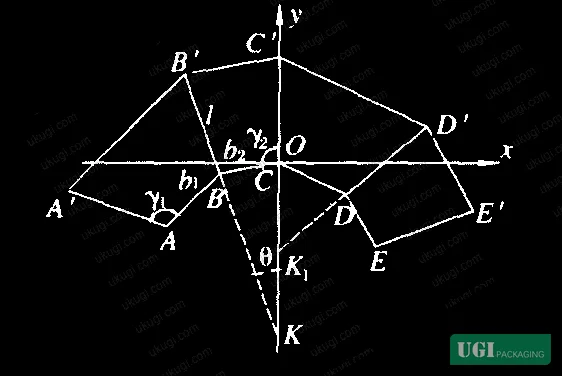
Where b₁ and b₂ are the two pairs of opposite bottom edge lengths (b₁ and b₂ in mm, corresponding to the two distinct rectangular dimensions), and γ₁ and γ₂ are the B-forming angles on adjacent, non-identical side panels.
This condition ensures that when the two outer panels fold inward along fold lines B′B and D′D, their outer edges A′A and E′E land in exact coincidence — which is the geometric prerequisite for the adhesive bonding zone to function and for the flat-collapsed blank to re-erect cleanly.
Design example from the source data: b₁ = 50 mm, b₂ = 40 mm, leg length l = 78 mm, γ₁ = 98.5°. Applying the condition yields γ₂ = 96.8°. The angular difference γ₁ − γ₂ = 1.7°, which is well within the maximum allowable differential of 10° when the minimum bonding angle δ_min is set to 40°.
The four geometric cases the analysis identifies:
| Condition | Box Shape | Auto-Lock Achievable? | Notes |
|---|---|---|---|
| γ₁ > γ₂ > 90° | Standard frustum, larger base | Yes, if b₁/b₂ = cosγ₁/cosγ₂ | δ < 45°; must verify δ ≥ δ_min |
| γ₁ < γ₂ < 90° | Inverted frustum, larger base at bottom | Yes, if b₁/b₂ = cosγ₁/cosγ₂ | δ > 45°; bonding strength adequate |
| γ₁ = γ₂ > 90° | Square-base frustum | Only when b₁ = b₂ (square frustum) | Rectangular base cannot use equal angles |
| γ₁ = γ₂ = 90° | Standard rectangular tube | Same conditions as conventional auto-lock | Reduces to the standard rectangular case |
Honestly, most buyers over-specify the taper angle as a purely visual parameter — steeper taper for shelf differentiation — without checking whether the resulting γ₁/γ₂ combination satisfies the cosine ratio. That is where costly tooling revisions originate.
Bonding Angle Constraints and Forming Interference #
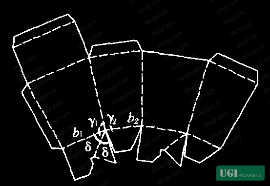
Getting the edge coincidence condition right is necessary but not sufficient. There is a second geometric parameter that controls whether the auto-lock bottom can actually be bonded with adequate strength: the bonding angle δ on flaps 1 and 3.
The bonding angle is calculated from:
δ = 45° + ½(γ₂ − γ₁)
This is derived from the A-forming angle α = 90° (fixed for rectangular-base cartons) and the forming angle differential between adjacent panels.
Two critical observations from the analysis:
- When γ₁ < γ₂ (inverted frustum), δ > 45°, which means bonding area is generous and adhesive strength is not a concern.
- When γ₁ > γ₂ (standard frustum, larger top opening), δ < 45°. As the angle differential increases, the bonding area shrinks. Below a minimum bonding angle δ_min, glue joint strength becomes inadequate for production line speeds.
In practice, the actual bonding angle used in production should be reduced 2–3° below the theoretical value to eliminate interference between the bottom flap and the side panel during formation. This interference is a real problem on high-speed auto-bottom forming equipment — if the flap contacts the panel wall during the folding sequence, the bottom will not lock reliably.
The constraint this imposes on design: when δ_min = 40°, the maximum allowable forming angle differential is:
γ₁ − γ₂ ≤ 10°
This is a hard limit. Designs that push γ₁ − γ₂ beyond 10° while using a 40° minimum bonding angle will produce intermittent auto-lock failures — not consistent failures, which makes them harder to catch in sampling.
In supplier qualification work, we have seen samples from three of six carton suppliers fail the auto-lock formation test on frustum designs precisely because the bonding angle was cut too close to the interference threshold. The failures were intermittent — roughly 1 in 8 units — which passed a 5-unit sample check but failed at 50-unit functional testing. The root cause in each case was a γ₁ − γ₂ differential of 12–14° combined with a dieline that did not account for the 2–3° interference reduction.
Structural Design Variables and Their Interaction #
Understanding the relationship between the four primary design variables — b₁, b₂, γ₁, γ₂, and l — is what separates a structurally competent dieline from a cosmetically correct one.
The leg length l (the slant height of the trapezoidal side panel, in mm) does not appear in the primary geometric condition equation (b₁/b₂ = cosγ₁/cosγ₂), but it directly controls the coordinate positions of the folded edge endpoints. In the coordinate model, the positions of key points A, A′, E, E′ after symmetric transformation are all functions of l. A longer leg length amplifies any angular error — meaning tolerances that appear acceptable on a compact 60 mm tall carton may produce visible misalignment on a 150 mm tall version of the same design.
Most procurement teams don’t realize that the standard rectangular tube carton auto-lock — the one they use on every other product — is actually a special case of this general frustum condition where γ₁ = γ₂ = 90°. When a design team migrates from rectangular to tapered cartons for a new product line, they often carry over the same structural logic without recognizing that the geometric constraints are materially different. The result is a dieline that looks correct in 2D layout but fails in 3D formation.
Current industry practice, at least among technically sophisticated carton manufacturers, is to validate frustum carton dielines computationally before cutting a sample die. The mathematical model described above is exactly the tool for that validation. For cosmetics packaging solutions and premium gift packaging solutions where tapered cartons are common, this pre-die computational check should be a standard step in the supplier qualification process.
Structural performance testing beyond geometric validation should follow ISO 2758:2014 Paper — Determination of bursting strength for board grade confirmation, and print surface specifications for finished cartons should align with ISO 12647-2:2013 Graphic technology — Process control for offset lithographic printing. For cartons destined for the food contact supply chain, compliance with EU Regulation No 10/2011 on plastic materials and articles intended to contact food applies to any inner coating or laminate layers.
Practical Guidance for Buyers #
If you are sourcing tapered folding cartons with auto-lock bottoms, the dieline is the product. A supplier who cannot demonstrate that their structural design satisfies b₁/b₂ = cosγ₁/cosγ₂ for your specific dimensions is guessing — and your production line or your customers will find the error.
Request the forming angle values γ₁ and γ₂ from the structural file before sampling. Calculate the cosine ratio and compare it to the b₁/b₂ ratio from your physical dimension spec. If they do not match within a reasonable tolerance (±0.5° is a workable threshold), send the dieline back for revision before any tooling is produced.
For inverted frustum designs (wider base, narrower top), the bonding strength concern largely disappears — δ will exceed 45° and the glue joint area is adequate. For standard frustum designs (wider top, narrower base), verify that γ₁ − γ₂ does not exceed 10° if your supplier is using a 40° minimum bonding angle specification. If they are using a tighter δ_min, the allowable differential is even smaller.
The supplier’s structural engineer should be able to produce the coordinate-transformed edge positions on request — this is basic computational dieline validation, not a specialized research capability. If they cannot, that is a qualification signal.
At ukugi.com, our Guangzhou-based structural team routinely performs this geometric validation on every frustum carton dieline before sample tooling is ordered — buyers initiating an RFQ for tapered auto-lock cartons can request the validation report along with the sample. We work with brand owners and procurement teams across North America, Europe, and Southeast Asia on exactly these kinds of structurally complex formats.
Need a custom formulation or sample? Request a quote from our team →
Supplier Qualification Questions #
- For the frustum carton design in our specification, can you provide the calculated values of γ₁ and γ₂ from your structural file and confirm that b₁/b₂ = cosγ₁/cosγ₂ is satisfied within ±0.5° tolerance?
- What is the bonding angle δ on flaps 1 and 3 in your dieline, and what minimum bonding angle δ_min does your specification apply — specifically, is it set at 40° or tighter, and does γ₁ − γ₂ comply with the resulting constraint?
- For the case where γ₁ > γ₂ > 90°, can you demonstrate via coordinate transformation analysis that outer edges A′A and E′E achieve full coincidence after folding along B′B and D′D — not just visual approximation on a sample, but a computed verification?
- What is the leg length l in your proposed dieline, and how does your structural validation account for the amplification of angular error at this leg length versus a baseline 60 mm format?
- Can you provide a physical 50-unit functional formation test result for this carton type, specifically documenting the rate of auto-lock formation success and identifying any interference events between the bottom flap and side panel during the folding sequence?
Sourcing Checklist #
- ☐ Dieline geometric condition verified: b₁/b₂ = cosγ₁/cosγ₂ confirmed within ±0.5° angular tolerance before tooling is cut
- ☐ Bonding angle δ confirmed ≥ 40° (δ_min) on flaps 1 and 3; for γ₁ > γ₂ designs, γ₁ − γ₂ ≤ 10°
- ☐ Actual bonding angle in production dieline reduced 2–3° below theoretical value to eliminate panel interference during formation
- ☐ Auto-lock formation functional test conducted on minimum 50-unit sample with ≥ 98% success rate (zero intermittent failures in 50 units)
- ☐ Board bursting strength tested per ISO 2758:2014 and result recorded in sample approval documentation
- ☐ For γ₁ = γ₂ conditions, b₁ = b₂ (square base) confirmed if equal forming angles are specified — rectangular base with equal angles cannot achieve auto-lock
- ☐ Structural engineer can produce coordinate-transformed edge positions (XA1, YA1, XE1, YE1) on request as documentary evidence of dieline validation
- ☐ Leg length l documented in structural specification; amplification effect on angular error assessed for leg lengths > 100 mm
Key Specifications Table #
| Parameter | Recommended Value | Verification Method |
|---|---|---|
| Geometric forming condition | b₁/b₂ = cosγ₁/cosγ₂ (within ±0.5° angular tolerance) | Coordinate transformation analysis on structural dieline; compare computed ratio to physical dimension ratio |
| Minimum bonding angle δ_min | ≥ 40° on flaps 1 and 3 | Calculate δ = 45° + ½(γ₂ − γ₁) from dieline forming angles; confirm against δ_min threshold |
| Maximum forming angle differential (γ₁ > γ₂ case) | γ₁ − γ₂ ≤ 10° when δ_min = 40° | Derived from constraint equation γ₁ − γ₂ ≤ 2(45° − δ_min); verify algebraically from dieline values |
| Interference reduction on bonding angle | Actual δ = theoretical δ minus 2–3° | Cross-section inspection of folded sample; confirm flap clears panel wall without contact during formation sequence |
| Auto-lock formation success rate | ≥ 98% over 50-unit functional test | Manual formation test: fold 50 blanks sequentially, count formation failures and interference events |
| Board bursting strength | Per project specification; test per ISO 2758:2014 | Mullen burst tester on conditioned samples; record kPa value against board grade specification |
Looking for a manufacturer that meets these specs? Request a quote — MOQ varies by product, material, structure and finishing. Product-specific MOQ is confirmed with each quotation.
References #
Data source: Geometric Conditions for Auto-Lock Bottom Formation in Rectangular-Base Frustum Folding Cartons, F.-D. Hou et al., Packaging Technology and Science, 2024
Frequently Asked Questions #
What is the key geometric condition for auto-lock bottom formation in a frustum folding carton?
The forming condition is b₁/b₂ = cosγ₁/cosγ₂, where b₁ and b₂ are the two distinct rectangular base edge lengths and γ₁ and γ₂ are the B-forming angles on adjacent non-identical side panels. This ensures the outer panel edges coincide exactly after folding, which is required for the adhesive bonding zone to function and for the carton to lock reliably.
Why does my frustum carton auto-lock fail intermittently rather than consistently?
Intermittent failures — typically 1 in 8 to 1 in 15 units — almost always indicate that the forming angle differential γ₁ − γ₂ is marginally exceeding the constraint for the specified minimum bonding angle. When the margin is small, thermal variation, board moisture content, and minor machine calibration differences push some blanks over the threshold and others not. The fix is to tighten the dieline so γ₁ − γ₂ is comfortably below the 10° limit (for δ_min = 40°), not to adjust production line settings.
Can an inverted frustum carton (wider bottom, narrower top) use an auto-lock base?
Yes. When γ₁ < γ₂ < 90°, the geometry satisfies the same b₁/b₂ = cosγ₁/cosγ₂ condition and the bonding angle δ will exceed 45°, meaning adhesive area is more generous than in a standard frustum configuration. Inverted frustum cartons with auto-lock bottoms are structurally more forgiving in production than standard frustum designs.
What happens if γ₁ = γ₂ with a rectangular (non-square) base?
This configuration cannot achieve auto-lock formation for a rectangular base. Equal forming angles on adjacent panels require b₁ = b₂ for the cosine ratio to hold — meaning only a square base frustum is compatible with γ₁ = γ₂. Specifying a rectangular base with equal forming angles is a dieline error that will produce consistent formation failure, not intermittent failure.
How does leg length l affect the forming tolerance?
The leg length l does not appear in the primary geometric condition equation, but it controls the magnitude of edge displacement at the folded position. A longer leg amplifies the effect of any angular error — a 1° deviation in γ that produces a 0.5 mm misalignment on a 60 mm carton will produce a 2+ mm misalignment on a 150 mm carton. For tall frustum cartons, the angular precision requirement on the dieline is correspondingly tighter.
Published by ukugi.com Technical Team | Request a quote


