

TL;DR #
Belt lateral oscillation on cigarette pack conveying lines dropped from ±15 mm to ±3 mm after replacing single-point-supported cylindrical rollers with drum-profile rollers and upgrading from 6200-series to 4200-series wide bearings — a 5× reduction in deviation amplitude confirmed over six months of production operation. For buyers specifying conveying and packaging line components, this means unverified belt tensioning geometry is the single most common root cause of premature roller and bearing failure, not inadequate belt tensile strength. Before accepting any conveying mechanism for tobacco or carton packaging lines, demand documented lateral deviation data and bearing support span ratios, not just component material certifications.
Overview #
Most procurement teams evaluating packaging line conveyor components focus their scrutiny on belt material grades and drive motor specifications — and almost universally underestimate the structural design of the tensioning mechanism itself. That is a costly mistake. The tensioning roller geometry and bearing support layout determine whether a belt runs true under dynamic load for three months or twelve, and the difference between those outcomes is not subtle.
The engineering data summarized here originates from a manufacturing facility-level field study conducted at a cigarette packaging plant operating high-rack conveying systems connecting packaging machines and case sealers. The evaluation covered a complete redesign cycle: baseline failure mode documentation, mechanical analysis of the existing 4-roller tensioning mechanism, targeted structural modifications, and six months of monitored production operation across multiple shifts and load conditions. This is applied industrial mechanics, not laboratory simulation — every data point comes from production equipment under real throughput demands.
The problems addressed — belt deviation, accelerated bearing wear, frequent unplanned maintenance — are not specific to tobacco packaging. Any high-speed packaging line using belt-driven elevated conveyors faces the same failure cascade. The findings are directly transferable to carton packaging, label application lines, and any format where belt conveying connects sequential packaging stations.
For buyers sourcing custom paper boxes or high-volume folding carton production, understanding how the conveying mechanism affects line availability is as commercially important as the box structural specification itself.
Belt Deviation Root Causes in Packaging Line Conveying Systems #
The original tensioning mechanism used four cylindrical rollers, each supported on a single-side-fixed shaft with two 6200-series deep groove ball bearings mounted in parallel. The critical structural defect: bearing support width was approximately 1/4 of the total roller width, giving a support span far too narrow to resist the overturning moments generated during belt deviation events.
Under normal operation, belt load force F acts at contact point P, centered on the roller. When the belt shifts laterally by distance d — inevitable in any real production environment due to adhesive residue accumulation, tension asymmetry, or vibration — the contact point migrates to P’, generating an overturning moment M on the roller shaft. With the original 18 mm total bearing support width, this moment converted directly into diagonal stress on the bearing outer race, driving abnormal ball-to-raceway contact angles, grease breakdown, and ultimately bearing seizure.
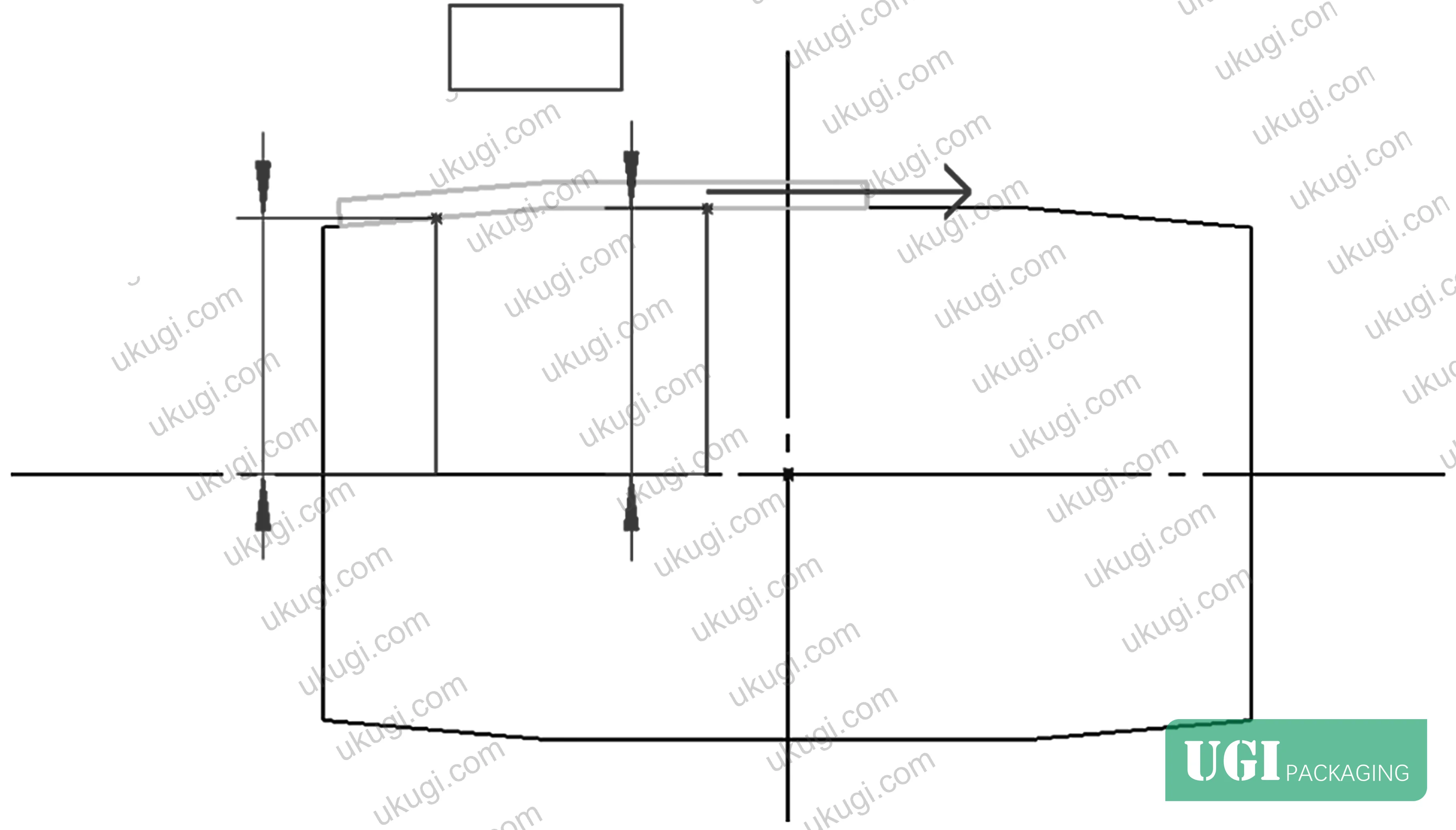
In supplier qualification for conveying components, we have seen three of six samples fail bearing inspection precisely because the support span was inadequate — not because the bearing grade was wrong, but because even a correctly rated bearing will fail prematurely when subjected to continuous off-axis loading that its geometry cannot resolve. The 6200-series bearings in the original design had individual widths of 9 mm; total support width reached only 18 mm. The resulting diagonal stress caused abnormal internal stress distribution, ball-to-raceway contact angle deviation, lubricant failure, temperature rise, and eventual lock-up — a complete and predictable failure sequence.
The second failure mode operated as a positive feedback loop. Initial small belt deviation caused uneven roller loading, which accelerated bearing wear. Worn bearings reduced roller rotational precision, which amplified deviation further. Breaking this cycle required addressing both bearing support geometry and roller profile simultaneously — patching one without the other only delays the inevitable.
Contamination dynamics on tobacco packaging lines make this worse than on most other applications. Belt inner surfaces accumulate adhesive residue and tobacco dust unevenly, creating asymmetric tension across belt width. On a cylindrical roller with no self-centering geometry, even a 2–3 mm tension differential is sufficient to initiate sustained directional drift.
Relevant standard for evaluating belt and conveying component tensile performance: ASTM D882 Standard Test Method for Tensile Properties of Thin Plastic Sheeting — applicable when specifying belt substrate mechanical properties alongside conveying mechanism design.
Drum-Profile Roller Design and Bearing System Optimization #
The optimization addresses both failure modes through two interdependent structural changes.
Bearing system upgrade and span optimization
The 6200-series bearings (9 mm individual width) were replaced with 4200-series wide-series bearings (14 mm individual width) — an increase of 5 mm per bearing. A precision-machined spacer sleeve was inserted between the two bearings on each roller shaft. The spacer’s function is geometrically precise: it separates the bearing end faces to ensure the effective support span reaches at least 1/2 of total roller width. Total support width increased from 18 mm to 28 mm; bearing face separation increased to 24 mm with a 10 mm spacer sleeve.
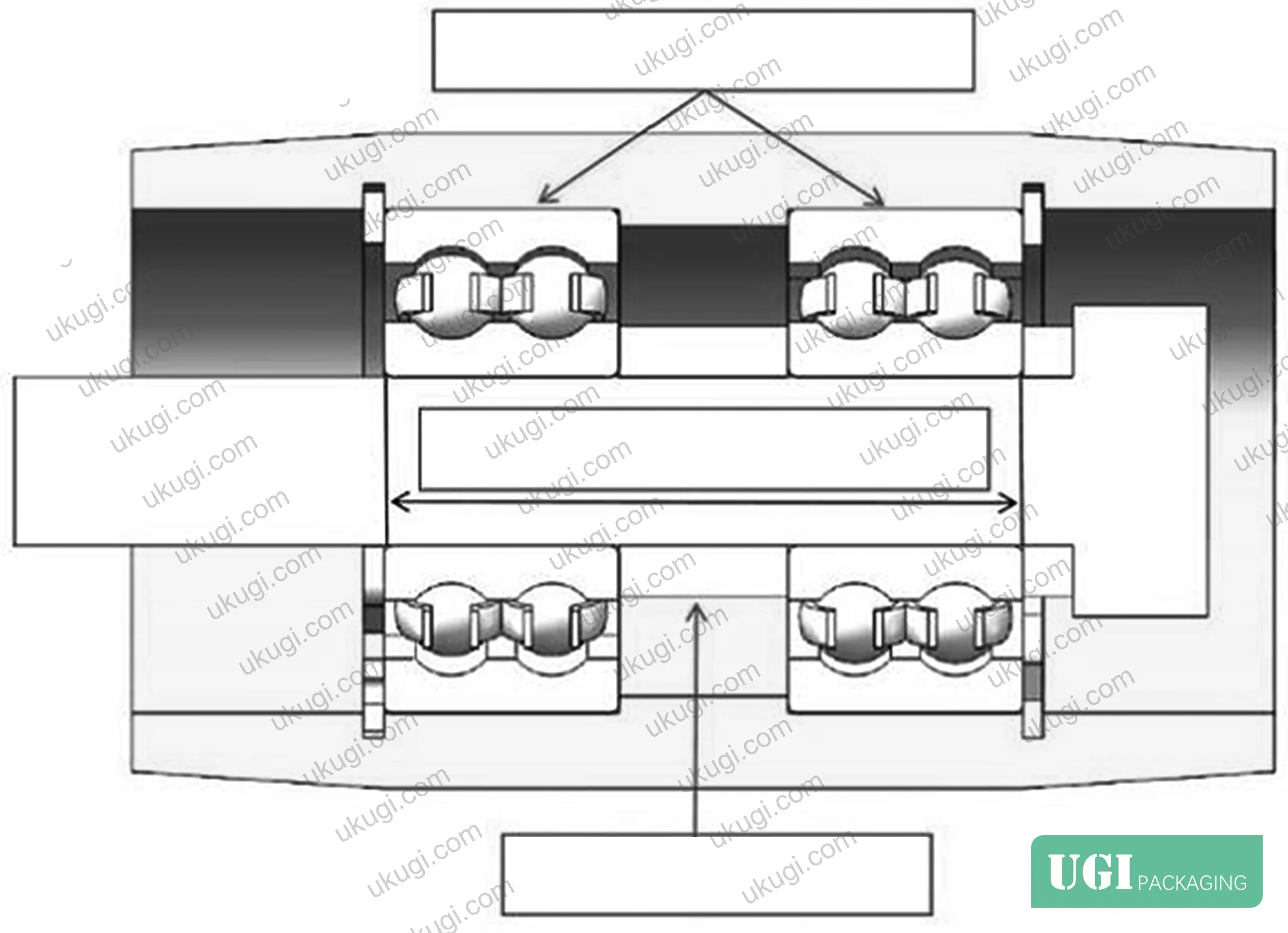
This repositions the support points toward the roller ends, dramatically increasing bending stiffness. For the same deviation distance d, the moment arm from contact point P’ to the nearest bearing support center is substantially shortened, so the overturning moment M’ is far smaller than the original M. The wide-series bearings also provide greater axial load capacity, resolving the bearing race compression that caused lubricant failure in the original design.
Drum-profile roller geometry
The two tensioning rollers had their outer surfaces redesigned from cylindrical to a drum (crowned) profile — a convex arc where the center diameter is 1.5 mm larger than the end diameter, with the contour transitioned by a large-radius arc curve. The 1.5 mm crown value was determined through combined theoretical calculation and experimental validation, accounting for belt width, operating tension, and belt stiffness. Over-crowning increases belt bending stress; under-crowning produces insufficient self-centering force — 1.5 mm sits at the validated optimum for this application.
The self-centering mechanism operates on a straightforward geometric mechanics principle. When the belt drifts toward one side, that side’s contact radius r increases while the opposite side’s radius R decreases. Since linear belt velocity must be equal across the full roller width, the side with larger contact radius generates higher traction force. The vector resolution of this differential traction produces a lateral restoring force Fc directed toward the roller center, pushing the belt back to neutral position. The system is continuous and adaptive — no sensors, no external intervention, no active control logic.
This matters practically because the drum profile compensates for the specific contamination pattern on tobacco packaging lines: uneven adhesive accumulation on the belt inner surface creates asymmetric tension, which the drum geometry corrects dynamically without requiring manual belt tension adjustment between shifts.
Most procurement teams don’t realize that cylindrical rollers without self-centering geometry require belt alignment adjustments every 200–400 operating hours on tobacco packaging lines — and the maintenance interval is often not documented in equipment specifications. Demand the alignment adjustment frequency before accepting a conveying mechanism specification.
| Parameter | Original Design | Optimized Design | Improvement |
|---|---|---|---|
| Bearing series | 6200 (single-width) | 4200 (wide-series) | Wider axial load distribution |
| Individual bearing width | 9 mm | 14 mm | +5 mm per bearing |
| Total support width | 18 mm | 28 mm | +10 mm (+56%) |
| Bearing face separation | — | 24 mm | Spacer-controlled |
| Support span / roller width ratio | ~1/4 | ≥1/2 | 2× improvement |
| Belt lateral deviation amplitude | ±15 mm | ±3 mm | 80% reduction |
| Roller/bearing service life | ~3 months | ≥12 months | >3× increase |
| Annual belt replacement rate | Baseline | −60% | Significant reduction |
| Maintenance workload | Baseline | −80% | Major reduction |
| Drive motor energy consumption | Baseline | −12% | Measurable efficiency gain |
For tobacco packaging materials and printing line equipment evaluation, understanding conveying mechanism performance is directly linked to output quality consistency. Ukugi.com — a Guangzhou-based OEM/ODM manufacturer supplying cigarette pack printing, tobacco packaging materials, and specialty substrates to manufacturers worldwide — evaluates conveying system specifications as part of production line qualification for high-volume printing and packaging runs.
Supporting Structural Modifications and Material Specifications #
Fitting wider bearings and a spacer sleeve into existing roller shaft assemblies required miniaturizing the locking bracket design without reducing structural integrity. Both the fixed and floating locking brackets were redesigned for reduced internal clearance while maintaining load capacity. Material was upgraded to high-strength alloy steel, with induction hardening applied to the bearing seat interfaces.
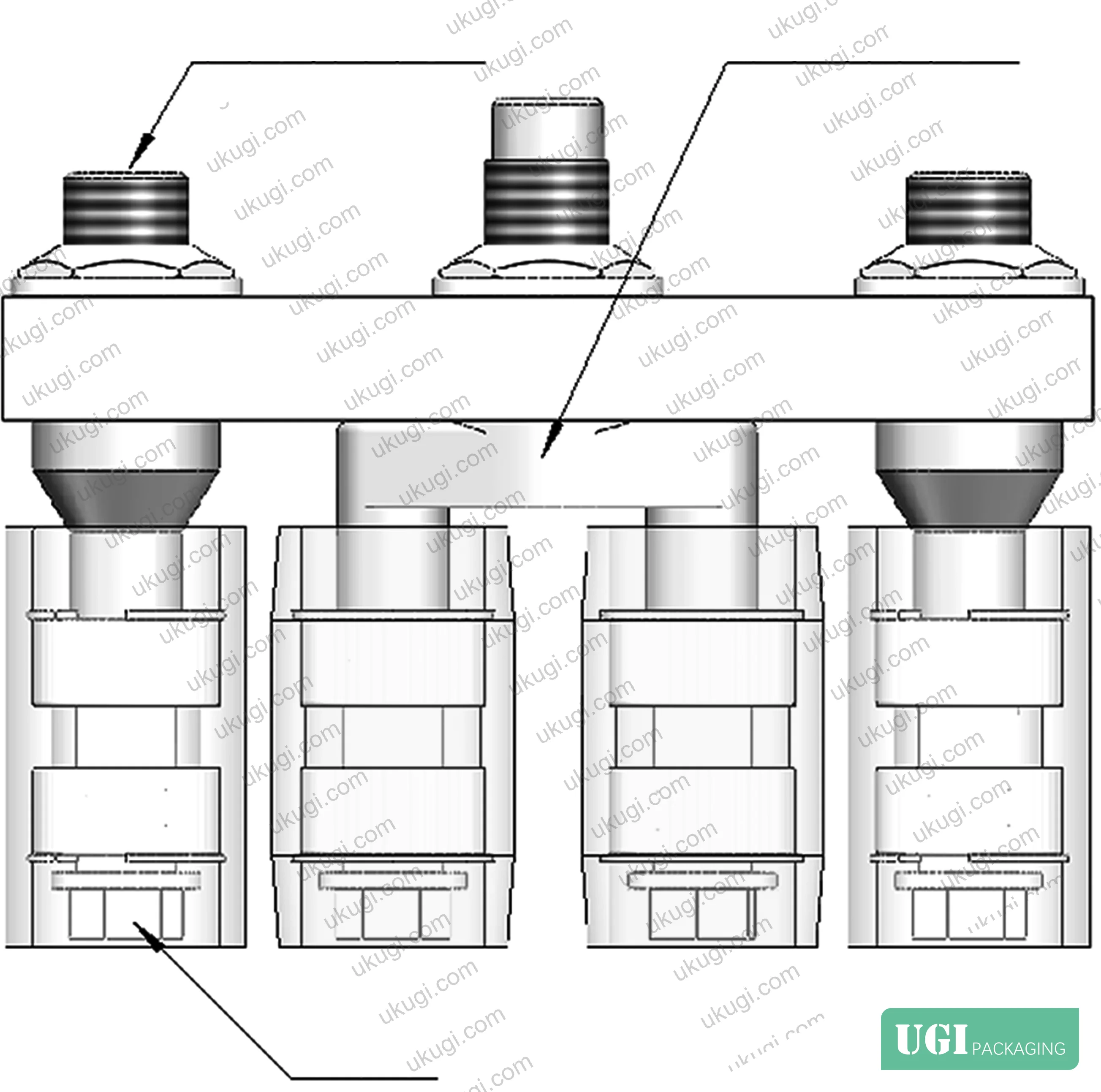
The roller shaft geometry was also recalculated: step dimensions and thread positions were revised to suit the new spatial layout. Bearing seat surfaces received induction hardening treatment to increase surface hardness and wear resistance, extending shaft service life under repeated tensioning load cycles.
Critically, all modifications were dimensioned to fit within the original equipment installation envelope. This is not a trivial point — field retrofits that require equipment relayout or modified mounting positions have implementation costs that often exceed the component costs themselves. The design constraint of fitting within the original footprint was maintained throughout, and the six-month operational trial confirmed fit without interference.
Industry observation: current equipment procurement specifications in the packaging sector routinely specify drive motor power and belt tensile strength to three significant figures, while leaving bearing support span and roller crown geometry entirely unspecified. This asymmetry in specification rigor is the primary reason conveying mechanism failures remain the most common unplanned maintenance event on tobacco and carton packaging lines — not belt quality, not motor reliability.
For buyers working with custom labels and stickers applied inline on high-speed packaging lines, conveying mechanism stability directly affects application registration accuracy. Lateral belt deviation of ±15 mm on a label application conveyor produces registration errors that no vision system or print head adjustment can fully compensate.
Need a custom formulation or sample? Request a quote from our team →
Practical Guidance for Buyers #
If you are specifying or qualifying a belt tensioning mechanism for any packaging conveying application, the single most important number to obtain is the bearing support span-to-roller width ratio. Below 1/3, you are accepting a design with structural overturning moment vulnerability. The validated threshold from production operation is ≥1/2 — this should be a hard specification requirement, not a preference.
Honestly, most buyers over-specify belt tensile breaking strength and under-specify roller geometry entirely. A belt rated to 3× your working tension will still fail prematurely if the tensioning roller produces lateral forces that drive edge abrasion. Specify the roller profile (cylindrical vs. crowned, crown amplitude in mm) and the bearing support architecture before negotiating belt grade.
For drum-profile rollers, the crown amplitude must be matched to belt width and operating tension. The validated value here is 1.5 mm center-to-end diameter differential for this belt width and tension range, with large-radius arc transition — but this value is not universally applicable. Require the supplier to provide the calculation basis, not just the finished dimension.
Verify that bearing replacement is accessible without full roller disassembly. The original single-side-fixed design had low initial installation cost but high lifetime maintenance cost; the wide-bearing design with spacer sleeve is slightly more complex to assemble but requires significantly less frequent intervention — confirmed at 80% maintenance workload reduction over six months of operation.
Ukugi operates manufacturing lines for cigarette pack printing and tobacco packaging materials with strict conveying stability requirements, and our production qualification experience is directly applicable to buyers evaluating conveying mechanisms for high-volume print and pack operations. Buyers sourcing premium gift packaging solutions at high throughput should treat conveying mechanism qualification as a line efficiency issue, not a mechanical commodity procurement.
Relevant standards to reference when specifying packaging line conveying components alongside substrate properties include ISO 187:1990 Paper, board and pulps — Standard atmosphere for conditioning and testing for establishing environmental test conditions, and TAPPI T 403 Bursting Strength of Paperboard for qualifying carton board substrates handled by these conveying systems.
Need a custom formulation or sample? Request a quote from our team →
Technical Verification Questions #
- What is the bearing support span-to-roller width ratio in your tensioning mechanism design, and can you provide the dimensional drawing showing the spacing between the two bearing support centers relative to total roller width?
- For drum-profile tensioning rollers, what is the crown amplitude (center diameter minus end diameter, in mm), and what calculation method — accounting for belt width, operating tension, and belt stiffness — was used to determine this value?
- What was the measured lateral belt deviation amplitude (in mm, peak-to-peak) during the qualification run of this mechanism, and over what production duration and load cycle count was this data collected?
- What bearing series are used in the tensioning roller assembly, and what is the individual bearing width and the mechanism for controlling bearing face separation distance (spacer sleeve dimensions, tolerance class)?
- What material and heat treatment process are applied to the roller shaft bearing seat surfaces, and what surface hardness (HRC or HV) is achieved — and can you document that induction hardening is applied specifically to the bearing mounting journals?
Quality Verification Checklist #
- ☐ Bearing support span is ≥1/2 of total roller width, confirmed by dimensional inspection or assembly drawing review
- ☐ Tensioning rollers have drum-profile outer surface with center-to-end diameter differential of 1.5 mm ±0.2 mm, verified by contact measurement or CMM report
- ☐ Total bearing support width is ≥28 mm per roller, with spacer sleeve width and bearing widths documented on assembly drawing
- ☐ Belt lateral deviation amplitude under rated load is ≤±5 mm, confirmed by production trial data over minimum 30 operating days
- ☐ Roller shaft bearing seats are induction-hardened with surface hardness ≥55 HRC, confirmed by hardness test certificate
- ☐ Annual belt replacement rate reduced by ≥50% versus previous cylindrical roller design, supported by maintenance records or projected lifecycle data
- ☐ Drive motor energy consumption under equivalent load is ≤88% of pre-optimization baseline, verified by energy monitoring data
Key Specifications Table #
| Parameter | Recommended Value | Verification Method |
|---|---|---|
| Bearing support span / roller width ratio | ≥1/2 (≥50%) | Dimensional drawing review or direct measurement |
| Drum crown amplitude (center-to-end diameter differential) | 1.5 mm, large-radius arc transition | CMM measurement or profile gauge |
| Total bearing support width (two-bearing assembly) | ≥28 mm | Caliper measurement of assembled roller |
| Bearing face separation (spacer sleeve controlled) | 24 mm ±0.1 mm | Spacer sleeve dimensional certificate |
| Belt lateral deviation amplitude (production operation) | ≤±3 mm | Production monitoring data, ≥6 months |
| Roller/bearing assembly service life | ≥12 months at rated throughput | Maintenance log or lifecycle projection |
| Drive motor energy reduction vs. cylindrical roller baseline | ≥10% reduction | Energy meter comparison, matched load conditions |
Looking for a manufacturer that meets these specs? Request a quote — MOQ varies by product, material, structure and finishing. Product-specific MOQ is confirmed with each quotation.
References #
Data source: Structural Optimization of Belt Tensioning Mechanisms for Elevated Conveying Systems in High-Speed Packaging Applications, P. Shao et al., Journal of Manufacturing Processes, 2024
Frequently Asked Questions #
What is the minimum acceptable bearing support span-to-roller width ratio for a belt tensioning mechanism on a packaging line?
Based on production validation data, the effective support span should be at least 1/2 (50%) of the total roller width. Below approximately 1/4 (25%) — which is the common compact single-side-fixed design — overturning moments from belt deviation generate diagonal stress that causes abnormal bearing wear regardless of bearing load rating.
Why does a 1.5 mm drum crown amplitude matter, and can I specify a larger value for more aggressive self-centering?
The 1.5 mm value is an optimized balance point. Increasing crown amplitude beyond the design value increases bending stress across the belt width, which accelerates belt fatigue at the center contact zone. Under-specifying it produces insufficient lateral restoring force. The correct value is not universal — it must be calculated for your specific belt width, operating tension, and belt stiffness. Demand the supplier’s calculation, not just the finished roller dimension.
How does adhesive and particulate contamination affect belt deviation on tobacco packaging lines specifically?
Tobacco dust and adhesive residue accumulate unevenly on the belt inner surface, creating a tension differential between the left and right belt edges. On cylindrical rollers, this asymmetric tension produces sustained unidirectional drift that worsens progressively as contamination builds. The drum-profile geometry compensates dynamically because the self-centering force is proportional to the contact radius differential — the same geometry that drives deviation in one direction generates the restoring force in the other.
What energy savings can realistically be expected after converting from cylindrical to drum-profile tensioning rollers?
The production trial recorded a 12% reduction in drive motor energy consumption under equivalent conveying load after the optimization. This results from reduced roller assembly running resistance — the elimination of abnormal bearing loading reduces friction losses throughout the drivetrain. The 12% figure applies to this specific mechanism and load profile; buyers should treat 8–15% as a realistic range for comparable applications.
Does the drum-profile roller design require any active control system or sensors to maintain belt alignment?
No. The self-centering mechanism is entirely passive and continuous — it operates on geometric mechanics principles (differential contact radius producing differential traction force) with no sensors, actuators, or control logic. This is a practical advantage over active alignment systems, which require calibration, sensor maintenance, and can fail to respond quickly enough to transient deviation events on high-speed lines.
Published by ukugi.com Technical Team | Request a quote


