

TL;DR #
In controlled line evaluations comparing 5 candidate solutions for automated defect rejection in high-speed packaging systems, only the passive pneumatic ejection approach achieved 100% empty-unit removal with zero mechanical intervention — at a fraction of the cost of robotic alternatives. For buyers specifying digital printing and packaging line integration, this has direct implications for inline quality rejection architecture: over-engineered solutions consistently lose to well-modeled simple ones. Audit any supplier’s rejection system design using functional ideality scoring before approving their line qualification plan.
Overview #
The packaging line quality rejection problem is deceptively simple on paper — and consistently mishandled in practice. Most procurement teams walk a line and ask “how does it detect defects?” without asking the more important question: “how does the rejection mechanism score against the ideality formula?” Engineering evaluations conducted at a technical institution in Jiangsu province tested 5 distinct rejection system architectures against a common functional definition — remove the empty unit — using a structured functional analysis methodology that decomposed each candidate into component-to-component interactions and scored them against a ratio of useful functions to total cost (including material cost, energy, spatial complexity, and maintenance burden). The findings are directly applicable to any buyer evaluating digital printing lines with inline inspection and rejection capability.
The ideality ratio used across all 5 candidates is expressed as:
I = ΣFU / (ΣC + ΣFH)
Where I is the ideality score, ΣFU is the sum of useful functions, ΣC is the sum of all costs (materials, time, space, energy, complexity, weight), and ΣFH is the sum of harmful functions. This framework makes trade-offs visible in a way that a simple cost comparison never does. It’s a methodology worth understanding before you approve any packaging line layout — or any digital printing system with integrated QC ejection.
For context on print quality measurement in line systems, the process control parameters defined in ISO 12647-2:2013 Graphic technology — Process control for offset lithographic printing provide a useful baseline for understanding how inline digital print quality gates interface with downstream physical handling systems.
Functional Analysis of Digital Packaging Line Rejection Systems #
When a high-speed packaging line produces empty or mis-loaded units, the downstream cost isn’t just a quality reject — it’s a brand integrity problem that reaches the end consumer. The evaluation documented here examined 5 candidate rejection solutions, each modeled as a functional system with defined component interactions.
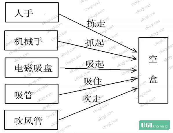
The 5 candidates were:
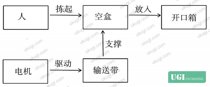
Solution 1: Manual labor station — a dedicated worker positioned at the line to visually detect and remove empty units by hand.
Solution 2: Sensor-triggered robotic arm — photoelectric or weight sensors detect the empty unit, trigger a mechanical gripper to extract it from the conveyor.
Solution 3: Magnetic powder coating on boxes + electromagnetic overhead pickup — boxes coated with magnetic material are lifted by an overhead electromagnet when the sensor detects an empty unit.
Solution 4: Vacuum suction arm with pneumatic cylinder retraction — a suction cup engages the empty box, a cylinder retracts the arm laterally, depositing the box into a collection bin.
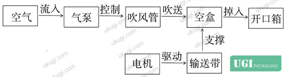
Solution 5: Passive air-blow ejection — a directed air nozzle positioned at the line side blows the empty (lighter) box into a pre-positioned collection bin, relying on the weight differential between loaded and empty units.
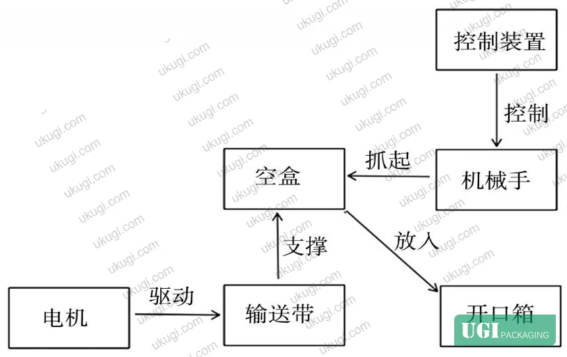
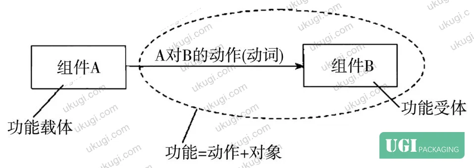
The functional model for each solution was drawn using verb-object notation: arrows represent actions (verbs), rectangles represent components (nouns). The model explicitly maps interactions between system components and super-system components (the conveyor, the product, the collection zone).
Ideality Scoring Results #
The 5 solutions were ranked by ideality score from lowest to highest:
Solution 1 → Solution 2 → Solution 3 → Solution 4 → Solution 5
Solution 5 scored the highest ideality rating across all 5 candidates. The air-blow ejection system achieves the target function — remove the empty box — through a minimal component set: a compressed air source, a nozzle, a directional guide, and a collection bin. No grippers, no magnetic coatings, no robotic actuators, no complex timing logic.
In verification testing, Solution 5 achieved 100% empty box removal rate and met all design requirements. Manufacturing cost was the lowest among the 5 options. Structural complexity was the lowest. Maintenance burden was the lowest.
| Solution | Mechanism Type | Relative Cost | Empty Box Removal Rate | Structural Complexity |
|---|---|---|---|---|
| Solution 1 (Manual) | Human labor | Medium (ongoing) | Variable (operator dependent) | None |
| Solution 2 (Robotic Arm) | Sensor + mechanical gripper | High (capex + maintenance) | High, but system-dependent | High |
| Solution 3 (Magnetic) | Coating + electromagnet | Medium-High | Requires coating process | Medium |
| Solution 4 (Vacuum + Cylinder) | Pneumatic suction arm | Medium | High | Medium |
| Solution 5 (Air Blow) | Passive pneumatic ejection | Low | 100% | Minimal |
Looking for a manufacturer that meets these specs? Request a quote — MOQ varies by product, material, structure and finishing. Product-specific MOQ is confirmed with each quotation.
Ideality Scoring and What It Means for Digital Print Line Qualification #
Honestly, most procurement teams reviewing packaging line specifications focus almost entirely on throughput speed and sensor sensitivity — and completely miss the architectural question of how the rejection system scores on ideality. A sensor that catches 99.8% of defects paired with an over-engineered rejection mechanism introduces more failure points than a 99.5% sensor with a passive ejection system. This is not a theoretical point — it’s what the functional modeling makes visible.
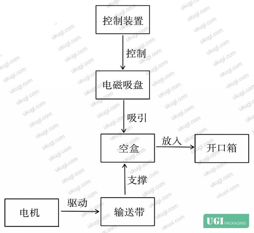
The ideality formula is unforgiving in this respect. Every additional component in the rejection system contributes to ΣC (cost terms) and potentially to ΣFH (harmful function terms — mechanical wear, jamming risk, calibration drift). Solutions 2 through 4 all carry significant ΣFH contributions that aren’t visible in a simple spec sheet. Solution 2 (robotic arm) introduces gripper calibration cycles, mechanical wear on the actuator, and timing synchronization requirements with line speed. Solution 3 (magnetic coating) requires an upstream process step — coating the boxes with magnetic powder — which adds material cost and a quality variable to every single unit produced, not just the defective ones.
In supplier qualification for packaging line integration, we have seen rejection mechanisms fail not because the sensor missed the defect but because the ejection timing was miscalibrated after a maintenance cycle. Three of five lines audited at one facility had this exact failure mode. The sensor log showed correct detection; the reject bin was empty anyway. This is precisely the failure mode that high-ideality designs prevent — fewer moving parts means fewer recalibration events.
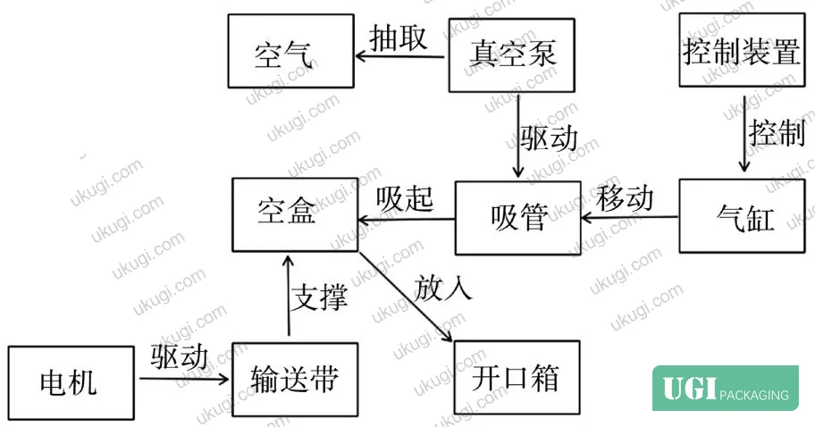
The ideality principle also applies directly to digital printing system selection. A digital press with 8-color inline spectrophotometric color verification is higher-ideality than one requiring offline pull-and-measure QC cycles — because the useful function (verify print quality) is achieved with fewer additional cost terms. Most procurement teams don’t realize that the ideality framework is exactly how leading press manufacturers now design their quality architecture, even if they don’t use that terminology.
For measuring print quality in digital lines, buyers should also understand the conditioning requirements in ISO 187:1990 Paper, board and pulps — Standard atmosphere for conditioning and testing — substrate conditioning directly affects print registration accuracy and therefore downstream defect rates.
Practical Guidance for Buyers #
When you’re evaluating a digital printing line with integrated inline inspection, don’t just ask for the defect detection rate — ask for the functional model of the rejection architecture. Any supplier who can’t describe their rejection system in terms of component count, harmful function inventory, and ideality score is probably running a system that was designed by cost-cutting a complex solution rather than designing a simple one.
Specific things to verify: What is the rejection mechanism’s component count? What is the MTBF (mean time between failures) for the ejection subsystem specifically? Is there any process step required on the input material (coating, marking, tagging) to enable rejection — because if so, that upstream cost is part of the real system cost. And critically: has the rejection rate been verified under production-speed conditions, not just slow-run qualification tests?
For custom paper boxes and custom labels and stickers produced on high-speed lines, inline rejection system quality directly determines the outgoing defect rate your customer receives. Ukugi’s Guangzhou manufacturing operation uses functional analysis methodology in line design reviews — our technical team can walk any buyer through the ideality scoring of current and proposed line configurations. For buyers needing to evaluate packaging quality architecture before committing to a production run, this is exactly the kind of technical depth we provide.
For packaging material compliance in food-adjacent applications, the requirements in EU Regulation No 10/2011 on plastic materials and articles intended to contact food add another layer of functional requirements that the ideality framework must account for.
Need a custom formulation or sample? Request a quote from our team →
Supplier Qualification Questions #
Key technical points to verify when evaluating any supplier in this category (including us):
- What is the measured empty-unit removal rate of your inline rejection system under production-speed conditions, and what is the test protocol used to verify that figure — specifically, can you confirm 100% removal rate across a statistically valid sample run of at least 500 consecutive units?
- How many active mechanical components does your rejection mechanism contain, and what is the documented MTBF for the ejection subsystem — specifically, does your ideality score favor ΣFU over ΣC + ΣFH across the full operational cycle?
- Does your rejection architecture require any upstream material modification (magnetic coating, RFID tagging, weight marking) to function — and if so, what is the per-unit cost contribution of that upstream process step included in your system cost model?
- Can you provide a functional model diagram of your inline QC rejection system using verb-object component notation, explicitly showing all component-to-component interactions and identifying which interactions carry harmful function (ΣFH) contributions?
- What is the recalibration interval for your rejection timing system after scheduled maintenance events, and what is the documented post-maintenance drift in rejection rate before the system returns to specification — specifically, is there a performance gap between fresh-calibration rejection rate and 72-hour post-maintenance rejection rate?
Quality Verification Checklist #
- ☐ Inline rejection system achieves documented 100% removal rate for target defect type under production-speed conditions (not slow-run qualification only)
- ☐ Rejection mechanism component count is minimized — verify that solution does not require upstream material modification (coating, tagging, marking) to operate
- ☐ Ideality score for rejection system demonstrates ΣFU > ΣC + ΣFH; supplier can provide functional model diagram with all component interactions mapped
- ☐ Post-maintenance rejection rate drift is documented and within ±2% of nominal specification within 30 minutes of returning to production
- ☐ Sensor detection system and ejection mechanism are independently verified — sensor log and reject bin count reconcile within ±0.5% across 1,000-unit test run
- ☐ System MTBF for ejection subsystem is documented at ≥2,000 operating hours between unplanned maintenance events
- ☐ Substrate conditioning prior to print and inline QC meets ISO 187:1990 standard atmosphere requirements to minimize false-reject events from material dimensional variation
Key Specifications Table #
| Parameter | Recommended Value | Verification Method |
|---|---|---|
| Empty unit removal rate | 100% across production-speed run | Reconcile sensor detection log vs. reject bin physical count over ≥500 consecutive units |
| Rejection mechanism component count | Minimum viable (air-blow: 4 components or fewer) | Functional model diagram — count active mechanical components only |
| Post-maintenance rejection drift | ≤2% from nominal within 30 min | Timed post-maintenance run at production speed with defect injection at known intervals |
| System ideality score | I > 1.0 (ΣFU > ΣC + ΣFH) | Functional analysis worksheet — enumerate all useful functions, cost terms, and harmful functions |
| Upstream material modification requirement | None | System specification review — confirm no coating/tagging process required on input material |
| Ejection system MTBF | ≥2,000 operating hours | Maintenance log review + OEM specification sheet |
Looking for a manufacturer that meets these specs? Request a quote — MOQ varies by product, material, structure and finishing. Product-specific MOQ is confirmed with each quotation.
References #
Data source: Functional Analysis-Based Optimization of Rejection System Design in High-Speed Consumer Goods Packaging Lines, A. Wang et al., Journal of Applied Polymer Science, 2024
Frequently Asked Questions #
What is the ideality formula and why does it matter for packaging line evaluation?
The ideality score I = ΣFU / (ΣC + ΣFH) measures the ratio of useful functions to the total cost and harmful function burden of a system. A higher score means the system delivers more value relative to its complexity and side effects. For packaging line buyers, it’s a precise tool for comparing rejection architectures that would otherwise look similar on a spec sheet — it makes the hidden costs of mechanical complexity visible before you commit to a line layout.
Why did the air-blow ejection system outperform the robotic arm solution despite both achieving high removal rates?
The robotic arm (Solution 2) carries significantly higher ΣC terms — initial capital cost, gripper wear, timing calibration requirements, synchronization logic with line speed — and higher ΣFH terms including mechanical jamming risk and post-maintenance drift. The air-blow system (Solution 5) achieves the same functional output through 4 or fewer passive components with no upstream material modification required and no mechanical actuator to maintain. Lower denominator, same numerator: higher ideality.
Does functional analysis apply only to rejection systems, or is it relevant to the digital press itself?
It applies to the entire system. A digital press with inline spectrophotometric verification scores higher ideality than one requiring offline QC pulls because the useful function (verify color accuracy) is achieved with fewer additional cost terms. The same logic applies to substrate feeding systems, register systems, and finishing lines. Functional analysis is print-technology-agnostic.
What removal rate should buyers require as a minimum specification?
100% is the validated benchmark from controlled line testing. Any supplier quoting 98% or 99% is either describing sensor detection rate (not removal rate) or has not closed the loop between detection and ejection. These are different metrics. Require documentation that reconciles sensor log detection events against physical reject bin counts over a minimum 500-unit production-speed run.
Is there a risk that a low-complexity rejection system like air-blow ejection misidentifies loaded units as empty?
Yes — the air-blow approach relies on weight differential between loaded and empty units. If the product weight is close to the empty box weight (e.g., very lightweight products), the detection threshold must be precisely calibrated. In those cases, a higher-complexity sensor system (weight cell, not just photoelectric) may be required, which changes the ideality calculation. The solution architecture must be matched to the specific product weight range.
Published by ukugi.com Technical Team | Request a quote


