

TL;DR #
At print sizes below 10×10 mm, standard inkjet QR code symbol grades consistently fall to 2.0(C) or lower — a grade that fails most retail scanner thresholds and GS1 compliance requirements. Buyers specifying variable QR codes on packaging must treat print size, aperture selection, and pre-cure configuration as hard engineering parameters, not press operator adjustments. Before approving any inkjet QR code production setup, require a full GB/T 23704 symbol grade report at your exact target print dimensions.
Overview #
The practical gap between “scannable” and “grade-compliant” is wider than most procurement teams expect — and the consequences of that gap are showing up at retail and in brand-track audits. Industry research conducted at a high-volume tobacco packaging print facility provides a detailed technical framework for diagnosing and correcting this problem. The evaluation used calibrated REA Vericube inspection equipment with a 660 nm light source, testing QR code symbol grades across nine print size increments (7×7 mm through 15×15 mm) under controlled inkjet conditions — a Fuji Samba piezoelectric printhead at 1,200 dpi, WS-01 ink, and 600×600 dpi output resolution at 120 m/min. Grading followed the eight-parameter model defined in GB/T 23704, which maps directly to the ISO/IEC 15415 framework used in international trade compliance.
The timing of this work is not coincidental. GS1 has formally initiated its Global Migration to 2D (GM2D) program, designating China’s Zhejiang Province as the world’s first GM2D demonstration zone, with a target of completing the global transition from 1D barcodes to 2D commodity codes before 2027. Every packaging operation that currently prints variable data codes needs to understand whether their inkjet symbol grades are migration-ready — because most are not.
GS1 General Specifications for barcodes and data carriers on packaging defines the minimum symbol quality thresholds that underpin this migration. Understanding how those thresholds are measured — and what degrades them in production — is the starting point for any serious qualification effort.
QR Code Symbol Grade Mechanics in Inkjet Production #
The grading system works by assigning a numeric score from 0.0(F) to 4.0(A) to each of eight independent parameters, then applying the lowest single score as the overall symbol grade. That “weakest link” logic is the reason good-looking codes still fail: one degraded parameter drags the entire grade down regardless of how well the others perform.
The eight parameters split into two categories:
Image-correlated parameters (assessed from the reference greyscale image): Symbol Contrast (SC), Modulation, Fixed Pattern Damage, Axial Non-Uniformity, Grid Non-Uniformity, and Modulation of Reference Decode.
Data-correlated parameters: Reference Decode and Unused Error Correction (UEC).
If Reference Decode fails — meaning the code cannot be decoded — the symbol grade is automatically 0.0(F) regardless of any other parameter values. UEC is a direct indicator of how much error correction capacity has been consumed; low UEC headroom signals structural fragility in the printed symbol.
Symbol Contrast is worth isolating here. When SC ≥ 70%, that parameter alone scores 4.0(A). Standard white-background / black-ink design is not just aesthetic convention — it’s the most direct path to maximizing SC and keeping that parameter off the critical path.
Size vs. Grade: The Data Buyers Need to See #
The following results were obtained under the controlled test conditions described above. These numbers are not theoretical — they are production samples measured with calibrated instrumentation.
| Print Size | Standard Inkjet Grade | Edge-Correction Mode Grade |
|---|---|---|
| 7×7 mm | 2.0(C) | 3.0(B) |
| 8×8 mm | 2.0(C) | 3.0(B) |
| 9×9 mm | 3.0(B) | 3.0(B) |
| 10×10 mm | 3.0(B) | 4.0(A) |
| 11×11 mm | 3.0(B) | 4.0(A) |
| 12×12 mm | 4.0(A) | 4.0(A) |
| 13×13 mm | 4.0(A) | 4.0(A) |
| 14×14 mm | 4.0(A) | 4.0(A) |
| 15×15 mm | 4.0(A) | 4.0(A) |
The breakpoint is obvious: below 10×10 mm in standard mode, you cannot reliably achieve a 3.0(B) grade. With edge correction enabled, that threshold drops to 7×7 mm achieving 3.0(B) — a meaningful improvement, but still not reaching 4.0(A) until 10×10 mm. For any buyer whose packaging dictates QR codes smaller than 10 mm due to surface area constraints, edge correction is not optional — it is the minimum configuration requirement.
Honestly, most buyers over-specify error correction level and under-specify print size. A high error correction level (H) increases data density, which reduces module size at any fixed print dimension, which degrades grades in exactly the range shown above. Getting the version, error correction level, and physical size aligned before committing to a production setup is a design decision, not a post-press fix.
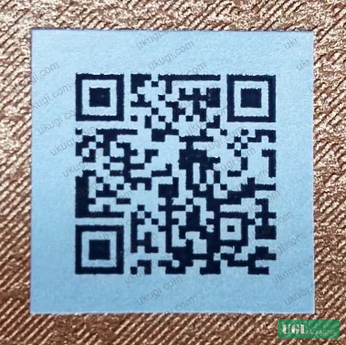
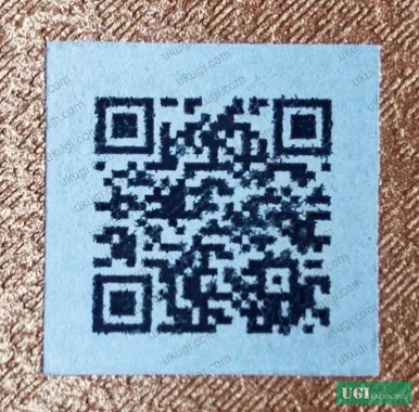
Critical Process Variables That Control Inkjet QR Code Symbol Grade #
Camera Lens and Measurement Aperture #
This is an area where supplier qualification processes routinely produce misleading results. The resolution capability of the inspection lens directly affects how strictly the symbol grade is assessed. A 25 mm focal length lens has a field of view of 37.5×27.7 mm and a minimum pixel size of 14.5 μm. A 16 mm focal length lens has a field of view of 63.5×47.5 mm and a minimum pixel size of 24.8 μm.
In supplier qualification, test results from the same physical QR code samples showed grade differences depending purely on which lens was installed. At 7×7 mm print size on a UV substrate, the 16 mm lens returned 2.0(C) while the 25 mm lens returned grades as low as 1.0(D) for the same sample. The 25 mm lens is more demanding at small print sizes precisely because its finer resolution exposes edge defects that the coarser 16 mm lens averages away.
International standards recommend a minimum effective resolution of 10 pixels per module width. Verify that your supplier’s inspection system meets this requirement at your specific module size — and confirm which lens they are using when they report grades to you.
Measurement aperture selection is equally critical. For matrix 2D codes, the aperture diameter must fall within 0.5X to 0.8X of the module width (X). Specific aperture selection by print size:
- 7×7 mm (X = 0.241 mm): use 5 mil (0.125 mm) aperture in manual mode
- 9×9 mm (X = 0.310 mm): use 8 mil (0.200 mm) aperture in manual mode
- 10×10 mm (X = 0.476 mm): use 8 mil (0.200 mm) aperture in manual mode
If the aperture is selected incorrectly — or left on automatic when automatic returns a non-compliant value — the reported grade is not valid. This is one of the most common technical gaps in incoming QR code quality inspections.
Printhead Height and Ink Management #
Printhead-to-substrate distance should be maintained between 0.5 and 3 mm in production. Deviation outside this range introduces dot placement variation that degrades Axial Non-Uniformity and Grid Non-Uniformity parameters — both image-correlated parameters that directly contribute to the final grade.
For dual-face (double-side) overlay printing used to achieve speeds above 200 m/min, registration between the two print faces is a major failure point. Standard dual-face control only overlays two identical QR patterns — when relative position shifts, the modules produce a “ghost” or double-image artifact that collapses grade scores. The engineering solution mirrors the trap logic used in multicolor offset prepress: the second face’s modules are inset by 2 pixels on the cross-feed axis using the physical printhead resolution. For a 1,200 dpi printhead printing a Version 3 QR code at 10 mm, each module is 0.345 mm wide and each pixel is approximately 0.021 mm. Insetting 2 pixels reduces each second-face module to 0.303 mm, with linear interpolation applied in the feed direction to maintain square modules and achieve accurate registration.
Most procurement teams don’t realize that high-speed inkjet QR printing above 200 m/min requires this dual-face pixel-level compensation — and most presses running at that speed do not have it enabled by default. It needs to be specified explicitly in the production setup requirements.
Pre-Cure Configuration for Flat-Sheet Inkjet #
This is where we saw the clearest failure mode in production evaluation. High-speed flat-sheet inkjet machines operating at 80–135 m/min have a typical gap of 1.5–2 m between the leading printhead and the LED UV cure lamp. On substrates with good surface wetting, ink spreads laterally before cure — producing visible “ink bleed” artifacts that directly degrade Modulation and Fixed Pattern Damage scores.
Two partial solutions exist: increasing line speed (flat-sheet machines generally cap at 150 m/min, which is insufficient to solve all bleed cases) or moving the cure lamp forward (physical constraints typically limit the minimum lamp-to-head distance to around 1 m, still too far to prevent spread on high-wetting substrates).
The effective solution is installing a dedicated LED pre-cure unit immediately behind the printhead array, positioned approximately 20–25 cm from the nozzle plate. At this distance, the pre-cure lamp arrests ink spread before diffusion occurs while remaining far enough from the printhead that UV scatter does not cause ink curing within the nozzle — a failure mode that blocks heads and requires full replacement.

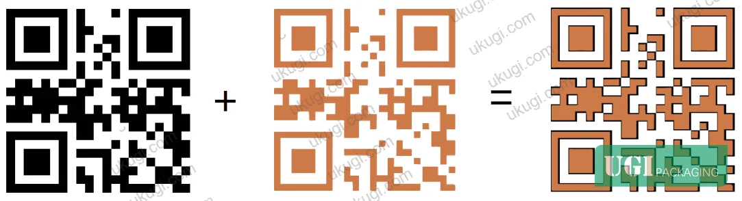
Production speed with pre-cure installed should be stabilized at 100–130 m/min for consistent symbol grade output.
Surface Dyne Value Pre-Treatment #
Direct inkjet printing onto varnished, UV-coated, or high-gloss laminated substrates introduces adhesion instability — a problem that appears intermittently rather than consistently, which makes it particularly dangerous in production batches. Installing a surface dyne pre-treatment unit in the substrate feed path ahead of the printhead modifies surface energy to match the ink’s wetting requirements. This simultaneously improves adhesion durability and stabilizes module edge definition, contributing to improved Modulation scores.
Practical Guidance for Buyers #
If you are sourcing packaging with inkjet-printed variable QR codes — serialized codes, track-and-trace, promotional campaigns, or GS1 2D compliance — the technical parameters above are your acceptance baseline, not suggestions.
Start with size. Any QR code smaller than 12×12 mm requires edge correction to be enabled at the press. Any code smaller than 10×10 mm requires additional scrutiny of the inspection setup — verify the lens focal length and confirm the measurement aperture is set in manual mode to the correct mil value for the actual module size. Require symbol grade reports at production speed, not at a reduced speed specifically set up for inspection.
Ask about pre-cure configuration for flat-sheet jobs. If a supplier is running flat-sheet inkjet at 80–135 m/min without a pre-cure unit, expect ink bleed on any substrate with surface treatment. This is a press configuration issue, not an ink issue, and it will not be solved by changing ink suppliers.
For high-volume or high-speed work, verify the dual-face registration control method. A press that runs above 200 m/min without pixel-level second-face compensation is producing codes with structural instability — grades may pass on the first day of production and degrade as registration drifts.
Ukugi.com operates as a Guangzhou-based OEM/ODM manufacturer with full inline digital printing capability, including inkjet variable data integration on folding cartons, flexible pouches, and specialty packaging substrates. Our team can assess your specific QR code size and substrate combination before committing to production specs. Need a custom formulation or sample? Request a quote from our team →
For buyers working with serialized packaging or brand security applications, our custom labels and stickers and hologram security stickers product lines integrate variable QR printing with security finishing — a combination that requires exactly the kind of symbol grade control detailed in this article.
Supplier Qualification Questions #
- What is your documented symbol grade floor for QR codes printed at 10×10 mm, measured per GB/T 23704 with a calibrated REA Vericube or equivalent instrument using a 660 nm light source — and can you provide batch test reports showing grade distribution across a production run?
- For flat-sheet inkjet jobs running at 80–135 m/min, do you have a dedicated LED pre-cure unit installed within 20–25 cm of the printhead, and what substrate dyne value range is your pre-treatment system designed to achieve before the ink strike?
- At print sizes below 10×10 mm, which measurement aperture mode do you use for symbol grade inspection — automatic or specified manual — and can you confirm the exact aperture value (in mil) used for module widths in the 0.190–0.250 mm range?
- For dual-face overlay inkjet printing at speeds above 200 m/min, what pixel-level registration compensation method do you apply to the second color face, and what is your maximum permitted registration offset in the cross-feed direction before a production run is halted?
- What is the printhead-to-substrate height specification for your inkjet QR code production setup, and what control mechanism maintains that height within the 0.5–3 mm operational window across variable substrate thicknesses?
Sourcing Checklist #
- ☐ Symbol grade report for the target QR code print size is provided at 4.0(A) for sizes ≥12×12 mm, or at minimum 3.0(B) for sizes ≥10×10 mm with edge correction enabled, per GB/T 23704 grading criteria
- ☐ Measurement aperture is confirmed as manually specified (not auto-selected) and falls within 0.5X–0.8X of the module width for the tested print size
- ☐ Inspection lens meets the minimum effective resolution of 10 pixels per module width at the target QR code dimensions
- ☐ Pre-cure LED unit is installed within 20–25 cm of the printhead for flat-sheet inkjet production, confirmed by equipment layout documentation or on-site inspection
- ☐ QR code quiet zone (blank margin) meets the minimum 4X requirement on all four sides at the stated production print size
- ☐ Dual-face registration offset is controlled via pixel-level inset compensation (second face inset ≥2 pixels at 1,200 dpi for module widths ≤0.345 mm)
- ☐ Symbol Contrast (SC) value is ≥70% on production samples, confirmed by parameter-level grade report (not only the composite symbol grade)
- ☐ Surface dyne pre-treatment is documented for any QR code inkjet run on UV-coated, varnished, or laminated substrates
Key Specifications Table #
| Parameter | Recommended Value | Verification Method |
|---|---|---|
| Minimum QR code print size for 4.0(A) grade | ≥12×12 mm (standard mode) or ≥10×10 mm (edge correction enabled) | GB/T 23704 symbol grade test at production speed |
| Measurement aperture diameter | 0.5X–0.8X of module width (e.g., 5 mil for X = 0.241 mm; 8 mil for X = 0.310–0.476 mm) | Manual aperture setting on calibrated 2D code verifier |
| Pre-cure LED unit distance from printhead | 20–25 cm | Physical measurement; confirm in equipment setup documentation |
| Production speed with pre-cure | 100–130 m/min | Press run log; symbol grade samples taken at stated speed |
| Printhead-to-substrate height | 0.5–3 mm | Mechanical height gauge; checked at job setup and substrate change |
| Symbol Contrast (SC) | ≥70% for 4.0(A) on this parameter | Parameter-level output from GB/T 23704 / ISO 15415 verifier |
| Dual-face pixel inset (1,200 dpi head) | 2 pixels per module edge (≈0.042 mm) in cross-feed direction | Print registration test chart; measured at operating speed |
| Minimum quiet zone | ≥4X on all four sides | Physical measurement against module width X at stated print size |
Looking for a manufacturer that meets these specs? Get a free sample — MOQ starts at 500 units.
For related packaging format applications, see our custom paper boxes range, which supports integrated inline variable QR code printing as part of the production workflow.
References #
Data source: Symbol Grade Enhancement Methods for Variable QR Code Inkjet Printing on Packaging Substrates, Q.-W. Gao et al., Journal of Printing Science and Technology, 2023
Frequently Asked Questions #
What is the minimum QR code print size for reliable 4.0(A) symbol grade in inkjet production?
Under standard inkjet conditions (600×600 dpi, 120 m/min, piezoelectric printhead), a 4.0(A) grade requires a minimum print size of 12×12 mm. With edge correction enabled, this threshold drops to 10×10 mm. Below 10×10 mm, even with edge correction, grades reliably reach only 3.0(B) in the tested configuration — adequate for some applications but insufficient for GS1 premium compliance tiers.
Why does changing the camera lens focal length affect the reported symbol grade?
It affects grade because the two focal lengths have different minimum resolvable pixel sizes — 14.5 μm for the 25 mm lens versus 24.8 μm for the 16 mm lens. The 25 mm lens resolves finer edge defects at small module sizes, which the 16 mm lens averages away. At 7×7 mm print size on UV substrates, this difference produced grade outcomes ranging from 2.0(C) to as low as 1.0(D) for identical samples depending on the lens used. Grades reported without specifying the lens configuration are not directly comparable.
What causes “ink bleed” on QR codes and why does it matter for symbol grade?
Ink bleed occurs when the delay between ink strike and UV cure is long enough for ink to spread laterally on high-wetting substrates. It directly degrades the Modulation and Fixed Pattern Damage parameters — two of the eight grading parameters — because module edges become soft and indistinct. This is a process configuration problem, not an ink formulation problem. The fix is a pre-cure LED unit installed 20–25 cm behind the printhead.
What is the GS1 GM2D migration and why should packaging buyers care now?
GS1’s Global Migration to 2D program is the industry-wide transition from 1D barcodes to 2D QR codes on retail packaging, with a global target completion before 2027. This means QR codes will become the primary machine-readable identifier on consumer goods packaging worldwide. Buyers who currently run variable data inkjet need to confirm that their production setups can reliably achieve the symbol grades required by GS1 standards — which are more stringent than basic “scannable” thresholds. The GS1 General Specifications for barcodes and data carriers on packaging is the applicable reference document.
Can the same inkjet setup be used across different substrate types — coated, uncoated, UV-laminated?
Not without adjustment. Each substrate type has different surface energy and wetting characteristics that affect ink spread rate, adhesion, and cure behavior. UV-coated and laminated substrates typically require surface dyne pre-treatment before inkjet to stabilize adhesion and module edge definition. Uncoated board is generally more forgiving but requires verification of SC values since low-brightness substrates reduce Symbol Contrast. The correct approach is to qualify the complete setup — printhead, ink, substrate, pre-treatment, and cure configuration — as a system, not to substitute individual components and assume grades will hold. Standards like ISO 187:1990 Paper, board and pulps — Standard atmosphere for conditioning and testing define baseline substrate conditioning requirements that should be met before any symbol grade qualification testing.
Published by ukugi.com Technical Team | Request a quote


