

TL;DR #
Ink temperature and drive voltage jointly determine dot formation quality in piezoelectric inkjet QR code printing, with temperature range 44–48°C and voltage range 29–33V producing the tightest dot geometry and fewest satellite defects. For buyers specifying variable QR codes on packaging — particularly tobacco packs, pharma cartons, or premium consumer goods requiring serialized “one item, one code” traceability — these two parameters are the primary controls to lock in during supplier qualification. Before approving any inkjet QR code supplier, require documented parameter sheets showing ink temperature, voltage, print speed, and head height settings alongside decoded QR grade results from production runs.
Overview #

Variable QR codes on packaging are not a novelty — they are fast becoming a compliance and brand protection requirement across tobacco, pharmaceutical, food, and consumer goods sectors. The principle of “one item, one code” — assigning a unique, scannable identifier to every individual unit — depends entirely on whether the inkjet printing system can reproduce that code with sufficient fidelity to decode reliably at speed. Most procurement teams treat this as a software or data management problem. It is not. It is a print process problem, and the failure point is almost always in the physics of droplet formation.
The evaluation framework in this article draws on controlled multi-variable trials conducted by a specialist industrial printing team, testing a single-sheet piezoelectric inkjet coding unit across four independent process parameters: ink temperature, drive voltage, print speed, and printhead standoff height. Each parameter was isolated — all others held constant — while dot geometry, satellite ink scatter, and QR symbol grade were measured on substrate. The dataset spans ink temperatures from 36°C to 50°C, drive voltages from 26V to 35V, and print speeds from 78 m/min to 145 m/min, providing a practical operating envelope that maps directly to production conditions. For readers unfamiliar with QR symbol grading, the relevant reference is GS1’s data carrier specifications — GS1 General Specifications for barcodes and data carriers on packaging define the decode grade thresholds that should form the floor of any supplier acceptance criterion.
The output is not a theoretical model. It is a parameter map: four dials, their interaction effects, and the quality consequences of miscalibration.
How Ink Temperature and Drive Voltage Control Digital QR Code Print Quality #
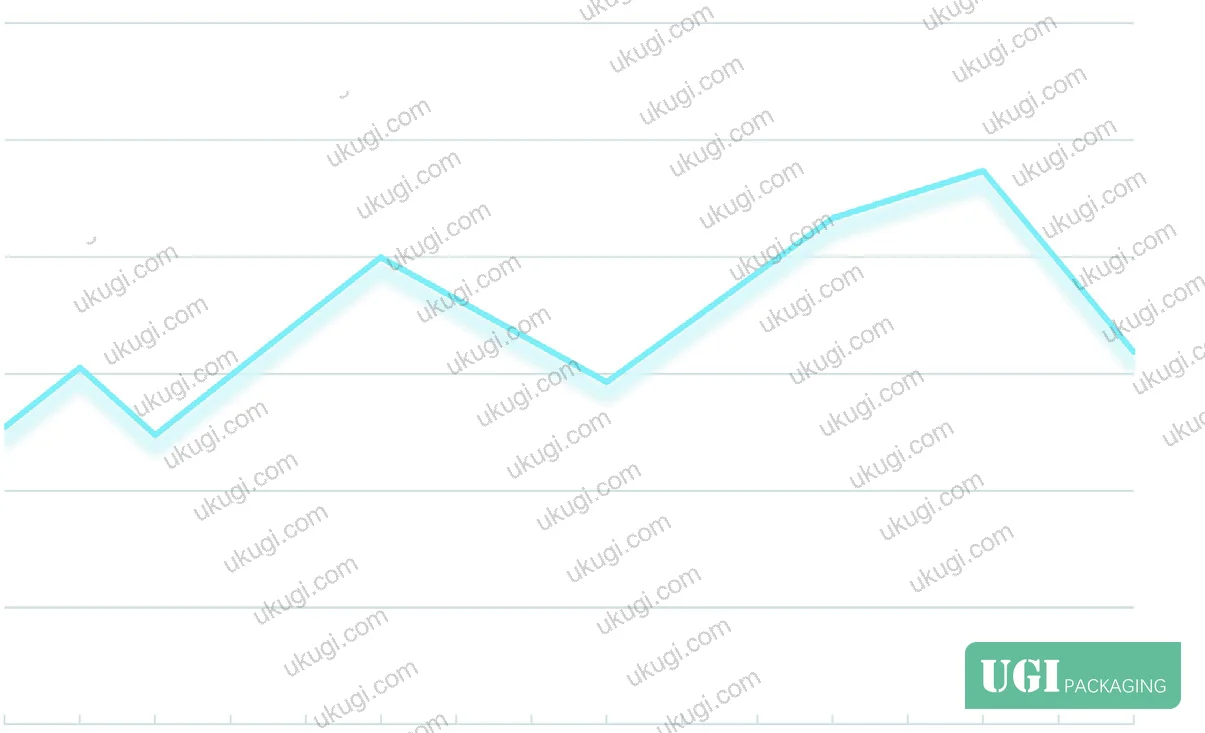

Piezoelectric inkjet operates by applying a voltage pulse to a piezo ceramic element adjacent to each nozzle. The ceramic deforms, generating a pressure wave that ejects a controlled volume of ink. The critical variable is ink viscosity — which is directly governed by temperature. At low temperatures, viscosity is too high: the ink resists full ejection, producing white spots (incomplete dot fill) and trailing lines (ink filament failure). At elevated temperatures, viscosity drops, flow improves, and these surface defects reduce. But go too high and the dot edge geometry degrades: chamfering and burring increase, giving an optically coarser appearance even though the dot area itself is not dramatically larger.
Measured data across the 36–50°C range shows that dot area variance remains relatively stable — the expansion in dot footprint from 36°C to 50°C is detectable but not large. What changes meaningfully is edge definition. The practical sweet spot is 44–48°C: white-point and trailing-line defects are suppressed, edge burring remains controlled, and viscosity is low enough for consistent droplet formation across all nozzles. Operating below 40°C is a quality risk on most substrates.
Drive voltage operates on a different mechanism. Voltage determines the ejection force applied to the ink column. Higher voltage increases ink mass per drop, raises initial droplet velocity, shortens the ink filament length, and consequently reduces satellite formation. Satellite droplets — the small secondary dots that land outside the intended dot position — are the primary cause of QR module contamination and grade degradation. At low voltage (26–27V), filament length is excessive and satellite scatter is pronounced. As voltage increases toward 31–33V, the filament breaks cleanly, main droplets consolidate, and print thickness increases slightly. The trials confirmed that voltage above 32V at 48°C ink temperature consistently produces the tightest dot geometry.
Voltage does not substantially alter the geometric shape of individual dots — that is controlled primarily by substrate surface energy and ink chemistry. What voltage controls is the fidelity of drop placement and the suppression of parasitic satellite ink.
| Parameter | Low Setting (Defect Mode) | Optimal Range | Effect of Exceeding |
|---|---|---|---|
| Ink Temperature | <40°C — white spots, trailing lines | 44–48°C | >48°C — edge burring, visual coarsening |
| Drive Voltage | <28V — satellite scatter, filament tails | 29–33V | >34V — overspray on fine modules |
| Print Speed | >130 m/min — droplet dispersion, QR distortion | 78–109 m/min | >130 m/min — grade degradation confirmed |
| Head Standoff Height | >nominal+3mm — filament elongation, scatter | Nominal (manufacturer spec) | +3mm or more — measurable scatter increase |
Print Speed and Printhead Height: The Variables Most Buyers Underestimate in Digital Printing #

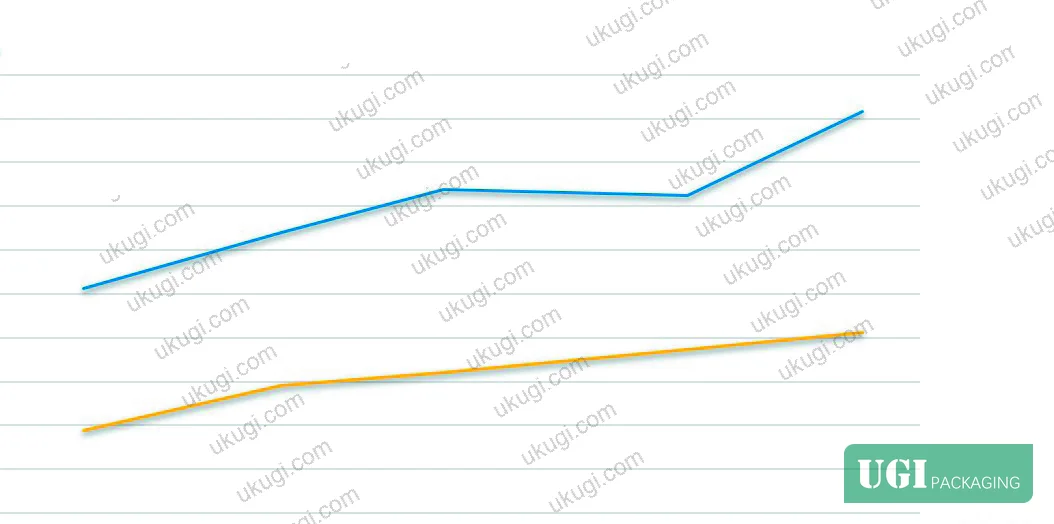
Honestly, most buyers over-specify QR code resolution and module size — and under-specify process parameters like head height and speed. The result is that a supplier can pass a lab-condition qualification sample and then fail in production because the line speed was increased to meet output targets.
The trials ran print speeds from 78 m/min through 95, 109, 130, and 145 m/min, at fixed voltage (32V) and fixed temperature (48°C), with printhead height at nominal and at nominal plus 3mm. The findings are direct: at 78–109 m/min with normal head height, droplet consolidation is good — the main ink mass arrives within a tight landing zone and secondary scatter remains below 0.4mm. At 130 m/min, droplet dispersion begins to visibly open up. At 145 m/min, the landing pattern is clearly degraded — dots spread, module edges lose definition, and QR symbol grade drops.
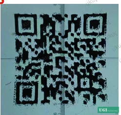
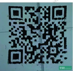
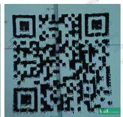
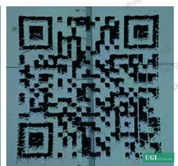
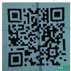
The head height effect compounds the speed problem. At nominal head height, the ink filament travels the design distance to the substrate, and surface tension breaks it cleanly into a single primary droplet. Raise the head 3mm above nominal, and filament length increases — the ink has more time to develop secondary filament instability before impact. At speeds above 109 m/min combined with +3mm head height, scatter distance increases to 0.9–1.0mm, which is severe enough to contaminate adjacent QR modules and cause decode failures.
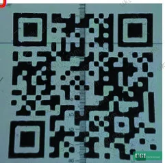
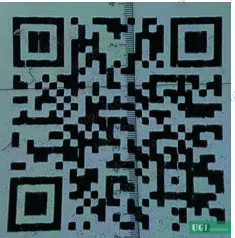
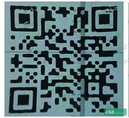
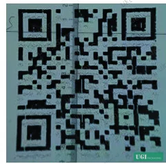
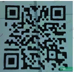
In supplier qualification, when the evaluation team ran five of the high-speed/elevated-head combinations, three of the five produced QR symbol grades that would not pass a standard traceability decode check. The failure mode was not random — it was entirely predictable once you understand the physics. Suppliers who run at maximum line speed to hit output targets are making a deliberate trade-off that buyers rarely see because qualification samples are run at reduced speed.
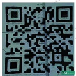
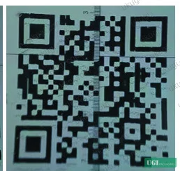
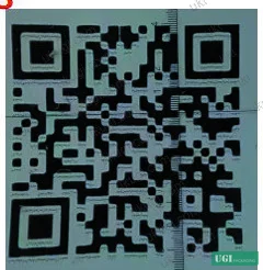
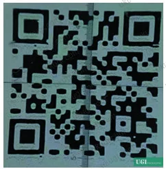
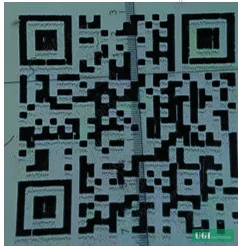
Most procurement teams don’t realize that the GS1 QR symbol grading criteria — covering parameters like modulation, reflectance margin, and decode grade — have been tightened in recent specification revisions, meaning legacy acceptance criteria written three or four years ago may no longer be adequate for current scanner performance requirements. If your QR acceptance test spec was written before your last equipment upgrade cycle, revisit it.
The relationship between print speed and head height is not linear — it is interactive. The safe operating zone is: print speed ≤109 m/min with head height at nominal. At 109 m/min with +3mm head height, scatter climbs to approximately 0.5–0.6mm — still marginal but borderline. Above that combination, failure is the expected outcome, not the exception.
For print conditioning test context, ISO 187:1990 Paper, board and pulps — Standard atmosphere for conditioning and testing governs the substrate conditioning environment — temperature and humidity variation at the substrate level can shift effective ink viscosity and change dot spread behavior independently of temperature setting, which is why controlled test environments matter for reliable parameter mapping.
Practical Guidance for Buyers #
If you are specifying inkjet-printed variable QR codes on packaging — whether for tobacco track-and-trace, pharmaceutical serialization, or consumer brand anti-counterfeiting — you need a parameter sheet from your supplier, not just a sample. The sample tells you what they can achieve at optimized settings; the parameter sheet tells you whether they have actually characterized their process.
The four parameters that matter are: ink temperature (target 44–48°C), drive voltage (target 29–33V), print speed (not to exceed 109 m/min for production runs requiring reliable QR grade), and head standoff height (locked at nominal, deviation ≤+1mm). Any supplier who cannot tell you the operating values for these four parameters — in writing, tied to a specific machine configuration — has not done the process characterization work.
For QR codes on tobacco packaging, cosmetics cartons, or any application where downstream traceability or consumer scan rates are tracked, specify the decode grade threshold in your purchase order, not just the visual appearance criterion. Visual inspection misses the satellite-scatter defects that cause intermittent scan failures in the field.
Ukugi.com is a Guangzhou-based OEM/ODM manufacturer producing custom packaging across labels, cartons, rigid boxes, flexible pouches, and specialty formats — including tobacco packaging with security printing capabilities. If your QR code specification is going onto custom labels and stickers or custom paper boxes and you need a supplier who has actually mapped the process parameters, not just sampled well, contact our technical team directly.
For applications requiring ink resistance verification, ISO 15397:2014 Printing inks — Determination of resistance to rubbing is the relevant standard for confirming that UV-cured QR code inks survive post-print handling without module degradation.
Need a custom formulation or sample? Request a quote from our team →
Technical Verification Questions #
- What is your documented ink temperature operating range for QR code inkjet printing, and at what specific temperature (°C) is your system calibrated for production runs?
- What drive voltage (V) do you use for your piezoelectric heads during QR code production, and can you provide print grade test results showing satellite scatter performance at that voltage versus the 26V and 35V boundary conditions?
- At what print speed (m/min) are your qualification samples produced, and can you confirm this matches your production line speed — specifically whether your production speed exceeds 109 m/min?
- What is the printhead standoff height (mm) relative to nominal during production, and do you have measurement records showing head height deviation is controlled within ±1mm?
- What QR symbol decode grade (using GS1 or equivalent grading protocol) do your production batches achieve, and can you provide the modulation and reflectance margin values from your inline inspection system?
Quality Verification Checklist #
- ☐ Supplier provides a documented parameter sheet listing ink temperature (°C), drive voltage (V), print speed (m/min), and head height (mm) for the specific machine configuration used for production
- ☐ Ink temperature during production is confirmed at 44–48°C — not just at setup, but logged across the production run
- ☐ Drive voltage is set within 29–33V range, with satellite scatter test results available showing scatter distance below 0.4mm at nominal head height
- ☐ Print speed does not exceed 109 m/min for QR code applications requiring reliable decode grade; supplier can provide grade data at production speed (not reduced-speed samples)
- ☐ Head standoff height is at nominal setting; deviation from nominal is documented as ≤+1mm, with evidence that elevated head height testing has been performed
- ☐ QR symbol decode grade meets specified minimum (e.g., Grade B or better per GS1 symbol quality criteria) confirmed by inline inspection system, not manual spot-check only
- ☐ Substrate conditioning environment meets controlled temperature and humidity conditions per ISO 187:1990 or equivalent, eliminating viscosity drift as an uncontrolled variable
- ☐ Incoming production samples show no visible white-point or trailing-line defects under 10× loupe inspection, confirming ink temperature and voltage settings are within qualified range
Key Specifications Table #
| Parameter | Recommended Value | Verification Method |
|---|---|---|
| Ink Temperature | 44–48°C | Thermocouple or inline temperature log on ink supply system; cross-check against print sample white-point defect count |
| Drive Voltage | 29–33V | Machine control panel setting recorded on job setup sheet; satellite scatter measured at <0.4mm on test substrate |
| Print Speed | ≤109 m/min (for grade-critical QR) | Production run log; compare qualification sample speed vs. production speed |
| Printhead Standoff Height | Nominal (manufacturer spec); deviation ≤+1mm | Mechanical gauge check at job setup; scatter distance measured at nominal vs. +3mm to confirm sensitivity |
| Satellite Scatter Distance | <0.4mm at nominal height, <0.6mm at +1mm deviation | Microscope measurement on substrate at production speed and temperature |
| QR Decode Grade | Grade B minimum; Grade A target for serialization applications | GS1-compliant inline vision system; decode rate ≥99.5% on 100-unit production sample |
Looking for a manufacturer that meets these specs? Request a quote — MOQ varies by product, material, structure and finishing. Product-specific MOQ is confirmed with each quotation.
References #
Data source: Process Parameter Optimization for Piezoelectric Inkjet QR Code Printing on Packaging Substrates, R. Feng et al., Journal of Printing Science and Technology, 2025
Frequently Asked Questions #
What is the most common cause of QR code scan failures on inkjet-printed packaging?
The most frequent cause is satellite ink scatter contaminating adjacent QR modules — caused by running at excessive print speed (above 109 m/min) or with printhead height above nominal, particularly when both conditions occur simultaneously. The failure is typically invisible to naked-eye inspection but causes intermittent decode failures at the consumer or supply chain scan point.
Does ink temperature affect the size of printed QR modules significantly?
The dimensional change in dot area across the full 36–50°C test range is measurable but relatively small — the more significant effect is on edge definition and surface defect count (white spots and trailing lines). Temperature primarily controls ink viscosity and therefore flow behavior, not dot size. The target range of 44–48°C suppresses surface defects without producing excessive edge burring.
Can a supplier run faster than 109 m/min and still produce acceptable QR codes?
Potentially, but only with compensating adjustments — specifically, lower head height (not higher), increased voltage to shorten filament length, and substrate surface energy matched to ink chemistry. Without those compensating factors, speeds above 130 m/min in the tested configuration produced consistent grade degradation. Any supplier claiming reliable quality above 130 m/min should be asked to provide decode grade data at actual production speed.
How do I specify QR code quality in a purchase order for packaging?
Don’t specify visual appearance only. Specify a minimum decode grade (e.g., Grade B per GS1 symbol quality assessment), a minimum decode rate on a production sample (e.g., ≥99.5% on 100 consecutive units), and require the supplier’s process parameter sheet to be submitted with each production batch. Tying payment terms to an incoming decode rate check is the most effective enforcement mechanism.
Is the parameter relationship the same for all inkjet head types?
The specific numeric thresholds (44–48°C, 29–33V, ≤109 m/min) are derived from piezoelectric head technology operating at standard ambient conditions. Thermal inkjet and continuous inkjet systems have different ejection physics and will have different optimal parameters. The framework — characterize each parameter independently, then verify at production conditions — is universal. The numbers are not.
Published by ukugi.com Technical Team | Request a quote


