

TL;DR #
In rotary die-cutting of pressure-sensitive labels, a die roller gap deviation of just 0.013mm above the 0.480mm standard was sufficient to cause visible burred edges on 40% of labels — making dimensional precision the single highest-leverage variable to control. For buyers sourcing custom label production, this means gap tolerance and die hardness specifications are non-negotiable acceptance criteria, not suggestions. Before approving any supplier for high-speed label production, request documented roller gap calibration records and ask specifically what gap value they run for your material thickness.
Overview #
If you’re evaluating suppliers for pressure-sensitive label production — particularly for high-speed autoapplication — the die-cutting bur problem is one of the most underestimated quality failure modes in the industry. Most procurement teams treat it as a press-operator issue. It isn’t. It’s a systems problem, driven by the intersection of die gap tolerance, material rheology, blade geometry, equipment wear, and environmental conditions.
The case analysis behind this article draws from documented production incidents across multiple label printing operations — ranging from beverage brand body labels running at 80–100m/min to medical device and cosmetics applications — each representing a distinct failure mechanism. The analysis was conducted by a practitioner with direct access to production floor measurement data, including roller concentricity readings, PSI logs, and material thickness sampling across batches. Field data consistently shows that ≥40% scrap rates are achievable purely from a single miscalibrated variable — and that recovery to≥99% yield is reproducible once root cause is correctly identified.
This applies directly to buyers specifying custom labels and stickers for consumer goods, electronics, pharma, or food applications. Die-cutting quality is not a back-end finishing concern — it determines whether your labels will run on automated application lines without jaming, peling, or failing cosmetic inspection.
Die Roller Gap Tolerance: The Primary Driver of Bur Defects in Rotary Die-Cutting #
Of all the root causes documented in production, roller gap deviation is the most consequential and the most commonly misdiagnosed.
In one well-documented case, a beverage brand label order required high-speed auto-application compatibility. Material specifications: 0.130mm face stock, 0.053mm glassine liner, liner standard tolerance±0.002mm. A newly commissioned die was set with62HRC hardness, 75° blade angle, and 0.432mm height — specifications that looked correct on paper. Die-cutting pressure was set at 800PSI, speed at 80–100m/min. Despite all these parameters appearing within range, approximately 40% of label edges showed visible burs immediately on startup, and the line required 1,500PSI to produce at all.
Field measurement identified the actual magnetic roller-to-anvil gap at 0.493mm — versus the 0.480mm specification. A gap deviation of 0.013mm was enough to prevent the blade from reaching the liner cleanly and consistently. The blade was physically not making contact with the substrate at the correct depth.
Gap was corrected to 0.443mm. Yield recovered to ≥99%.

This is a critical distinction: the failure was not visible in the tool spec sheet, not visible in the material COA, and not diagnosable without direct gap measurement. Most quality audits miss this entirely because they focus on documentation rather than live equipment measurement.
The adjustment also reveals a subtlety worth flaging: correcting the gap to 0.443mm — narrower than the nominal 0.480mm specification — was necessary to compensate for accumulated system variables. This is not a deviation to make arbitrarily. It introduces its own downstream risks (liner strike-through under high-tack materials), which need to be monitored separately.
Material Adhesive Tack: The Hidden Cutting Resistance Factor #
High-adhesion materials create a failure mode that standard blade geometry cannot resolve through hardness or angle alone.
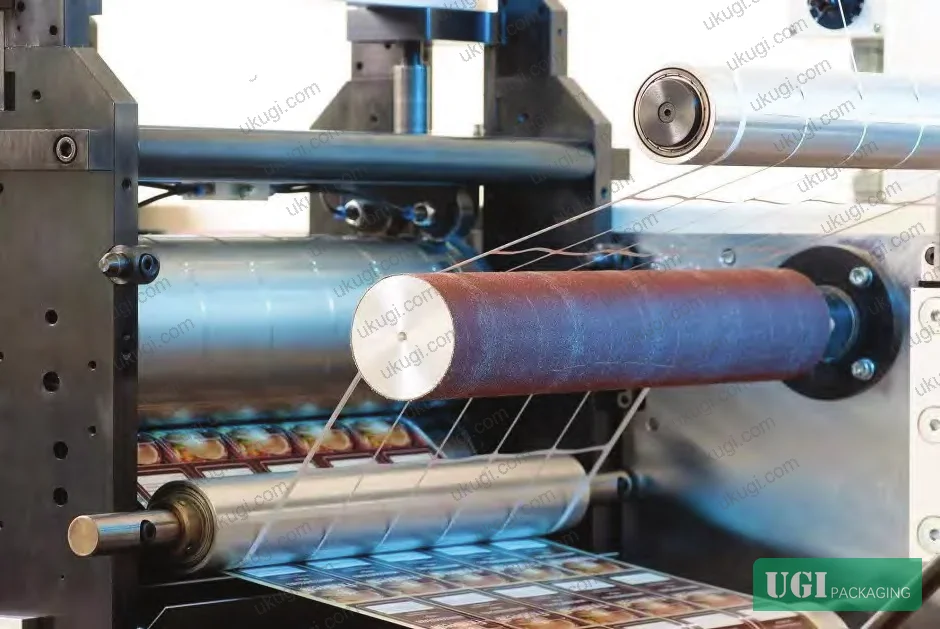
In one electronics component label case, the specification called for a high-tack pressure-sensitive adhesive at 800g/25mm peel strength, with a 0.120mm material thickness (±0.003mm tolerance). The die was a purpose-built sharp tool at 65HRC hardness and 50° blade angle. Die-cutting pressure ranged 600–2,000PSI, speed 50–100m/min. Despite these aggressive parameters, approximately 40% of edges showed severe adhesive bleed-out buring during trial production.
The mechanism: the adhesive grabbed the blade face during the cutting stroke, increased cutting resistance, and then pulled partially-cut material during the blade’s return travel. The material wasn’t failing to cut — it was being deformed after the cut was initiated.
Resolution: introduction of approximately 0.05ml/m² release agent during die-cutting, combined with reducing die speed to 60m/min. Long-term fix: nano anti-adhesion coating applied to the blade surface. Yield recovered to ≥99%.
The important procurement implication: if your label spec includes adhesive tack above 500g/25mm, you should be asking your die-cutter specifically about blade surface treatment and release agent protocols. A standard hardened tool will not be sufficient.
Equipment Degradation, Material Batch Variance, and Environmental Conditions as Secondary Bur Drivers #
Beyond die gap and material tack, field data documents several additional failure categories — each with distinct diagnostic signatures.
Pressure system aging. In one medical device label production case, the pressure control system showed severe wear. Instantaneous pressure exceeded the 800PSI set point by 30% (to over 1,040PSI), and at other moments dropped20% below set point to approximately 640PSI. This variance was batch-to-batch and unpredictable. Resolution required replacement of the roller unit and pressure components, with stabilized pressure control verified to within ±3% of set point. Yield recovered to ≥99%, with a reported 30% efficiency improvement.
Equipment concentricity failure. In a food label application, a small-format print operation encountered both torn-edge and adhesive-bond bur types simultaneously — a signature of uneven pressure distribution across the die width. Investigation found the magnetic roller had a maximum runout deviation of 0.060mm. After bearing replacement and roller repair, diameter and concentricity were both brought within0.003mm. Die pressure was reset from 1,200PSI to 600PSI initial, speed adjusted from 60to 90m/min. Bur problems resolved.
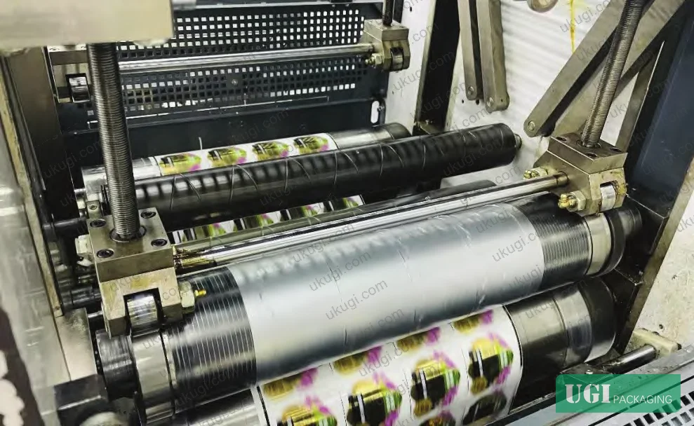
Material thickness non-uniformity. A cosmetics brand label case involving imported pressure-sensitive material (nominal 0.100mm, ±0.005mm tolerance, 65g/25mm tack) demonstrated what happens when material thickness variation exceeds specification — in this case dramatically so. Batch testing found material ranging from 0.045mm (0.055mm below nominal) to 0.145mm (0.045mm above nominal). Thin zones were over-cut; thick zones were under-cut. Both produced burs. Supplier replacement of the batch resolved the issue entirely.
Honestly, most buyers over-specify blade hardness and angle when they should be over-specifying material incoming inspection criteria. A 65HRC blade running into a 0.055mm-undersized substrate will always produce defects — no matter what the tool datasheet says.
Die-cutting speed vs. material compatibility. This one is consistently underestimated. In one electronics label case with material at 0.120mm (±0.005mm), 700g/25mm tack, and blade at 71HRC / 60° angle: production was clean below 60m/min. Above 60m/min, burs appeared consistently. The blade simply could not complete the cut within the contact window at that speed. Resolution: blade angle revised to 50°, equipment serviced to high-precision state. Speed capability recovered to 90m/min, yield≥99%.
Environmental temperature and humidity. A production facility in the Pearl River Delta region encountered summer adhesive-bleed buring on a 0.180mm material (±0.006mm, 750g/25mm tack). Equipment and tooling checked out normal (blade at 70HRC, 60° angle). Root cause: elevated temperature and humidity increased adhesive flow rate and blade adhesion. Resolution: production environment controlled to 22–25°C, 50–60% relative humidity. Pre-production material drying was added. Nano anti-adhesion blade coating applied per tooling supplier recommendation.
For material conditioning and testing environment standards, refer to ISO 187:1990 Paper, board and pulps — Standard atmosphere for conditioning and testing, which provides the baseline environmental requirements applicable to pressure-sensitive stock conditioning.
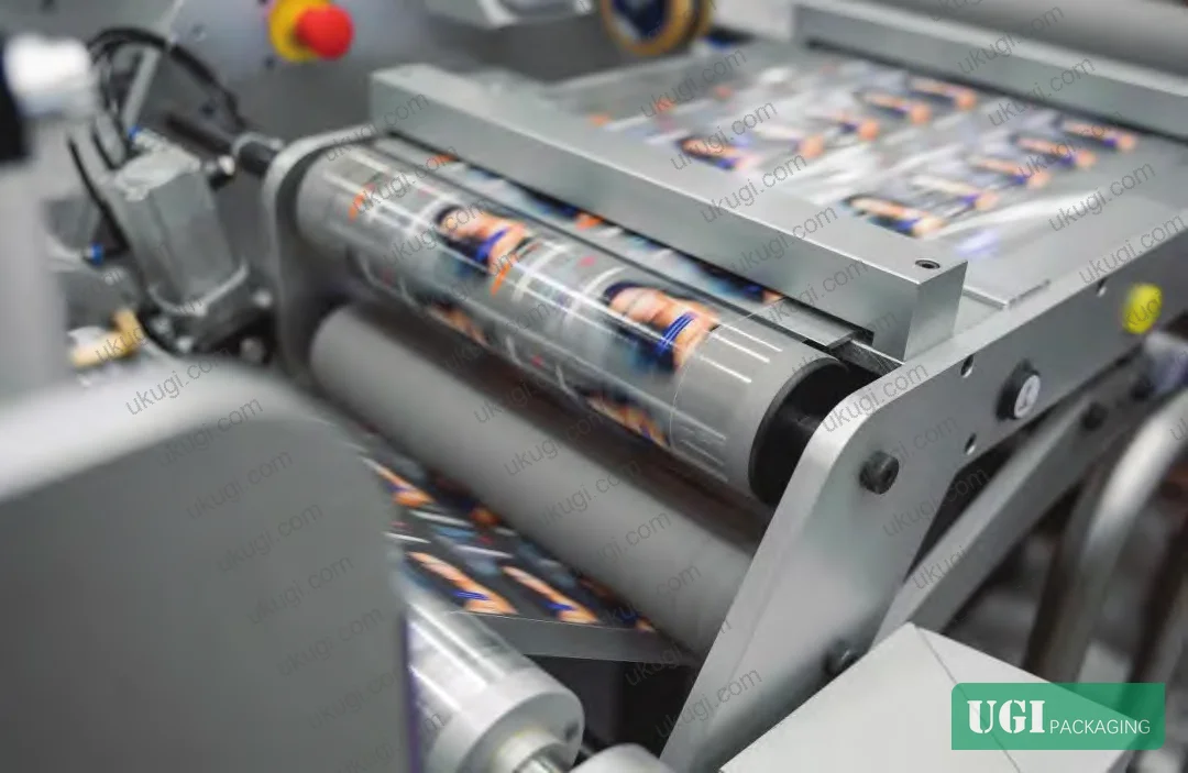
Blade material quality and maintenance. A chronic low-level bur problem at one large-format operation persisted despite all parameter adjustments. Investigation revealed that blades from different suppliers — even with nominally identical hardness and angle specifications — had significantly different steel grades, edge roughness, and toughness. Extended storage caused pitting corosion and coating degradation on blade faces. Supplier consolidation plus a regular blade inspection and replacement protocol resolved the issue.
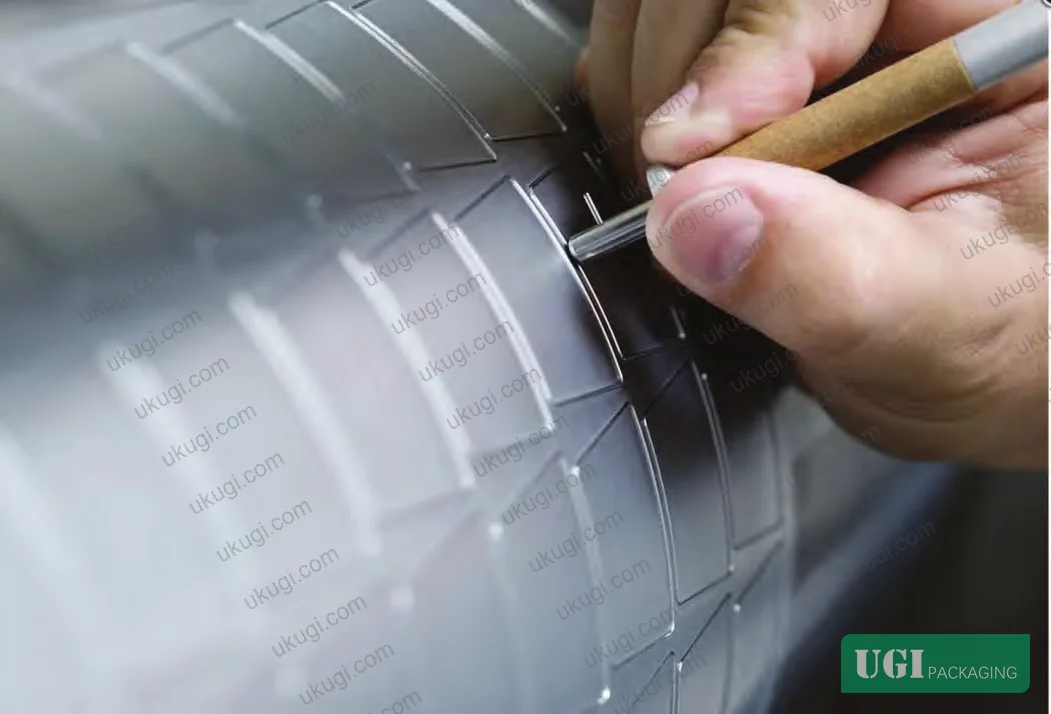
Most procurement teams don’t realize that blade hardness ratings from different suppliers are not directly comparable — a 65HRC value from a generic tool steel and from a specifically formulated die-cutting steel are not the same material behavior. The industry hasn’t standardized on this, and buyers are generally not aware it’s even a variable.
Practical Guidance for Buyers #
If you’re qualifying a label converter for a high-volume, automated application program, the single most important pre-production check is live roller gap measurement — not documentation review. Ask for the as-run gap value, not the tool nominal spec.
For materials with tack above 600g/25mm, confirm that the die-cutter has blade surface treatments (nano anti-adhesion coating, PTFE, or equivalent) and has documented speed-tack compatibility data for your specific substrate. Don’t assume this is standard — in supplier qualification, we’ve seen operations running high-tack materials on uncoated blades with no release agent protocol in place.
Material batch consistency is a sourcing-side problem, not just a production-side problem. Require incoming material thickness data (measured, not just supplier-stated) and set contractual rejection criteria:±0.003mm for standard stock, ±0.005mm for premium imports. A batch ranging from 0.045mm to 0.145mm nominal — as documented in one cosmetics label case — should never reach a die-cutting line.
For label designs with tight curves, re-entrant angles, or blade-corner features, work with your converter early. Sharp interior angles create non-uniform blade loading that no amount of pressure calibration can correct after the tool is made.
At ukugi.com, our production team operates rotary die-cutting lines for custom labels and stickers and hologram security stickers — with documented gap calibration records available per batch and material compatibility testing conducted before production sign-off. We produce for international brand owners across North America, Europe, and Southeast Asia, and our RFQ process includes a material-tool compatibility review as standard. Need a custom formulation or sample? Request a quote from our team →
Technical Verification Questions #
- What is the actual measured roller gap value you run for a 0.130mm material with 0.053mm glassine liner — and how does that compare to the nominal die height specification? Provide the last calibration record showing measured gap vs. specified gap.
- For materials with adhesive tack ≥600g/25mm, what blade surface treatment do you apply, and at what release agent application rate (ml/m²) do you operate? Provide a documented example from a previous run.
- What is your pressure control system stability specification — what is the maximum allowable deviation from set point PSI, and how do you verify it? (Acceptable answer: ±3% or tighter, verified by pressure logging during calibration.)
- What is your incoming material thickness inspection protocol — do you measure actual batch thickness distribution, and what is your rejection threshold for thickness deviation beyond nominal tolerance?
- What is the maximum concentricity (runout) tolerance you maintain on your magnetic rolers, and when was the last concentricity measurement taken on the die unit that would run our job? (Acceptable threshold: ≤0.003mm runout.)
Quality Verification Checklist #
- ☐ Roller gap measured (not just specified) and documented within±0.005mm of the target value for the submitted material thickness
- ☐ Blade Rockwell hardness confirmed ≥62HRC and blade angle appropriate for material tack (50° for tack ≥700g/25mm; 60–75° for standard tack)
- ☐ Incoming material thickness distribution measured across batch — maximum deviation within stated tolerance (e.g., ±0.003mm for standard, ±0.005mm for premium)
- ☐ Pressure system stability verified within ±3% of set point PSI across a full production run log
- ☐ Magnetic roller concentricity confirmed≤0.003mm runout per most recent calibration measurement
- ☐ Production environment temperature controlled to 22–25°C and relative humidity to 50–60% per ISO 187:1990 conditioning requirements
- ☐ Die-cutting speed validated against tack level — speed confirmed below the bur threshold for the specific material (e.g., ≤60m/min for 700g/25mm tack unless blade angle is corrected to 50°)
- ☐ First-off sample batch yield documented at≥99% pass rate before full production approval
Key Specifications Table #
| Parameter | Recommended Value | Verification Method |
|---|---|---|
| Roller gap (0.130mm face / 0.053mm liner) | 0.443–0.480mm | Direct gauge measurement; document as-run value vs. nominal |
| Blade Rockwell hardness | ≥62HRC (standard); ≥65HRC for tack ≥700g/25mm | Rockwell hardness tester on blade face before mount |
| Magnetic roller concentricity (runout) | ≤0.003mm | Dial indicator measurement at roller OD, logged per service interval |
| Pressure system deviation from set point | ≤±3% of set PSI | Pressure transducer logging over minimum 10-minute production run |
| Material thickness tolerance (incoming) | ±0.003mm standard; ±0.005mm max | Micrometer sampling across batch width and length |
| Die-cutting speed (700g/25mm tack) | ≤60m/min with standard blade; up to 90m/min with 50° blade angle | First-article trial with edge inspection at incremental speed steps |
| Production environment — temperature | 22–25°C | Calibrated thermometer, continuous monitoring in die-cutting area |
| Production environment — relative humidity | 50–60% RH | Calibrated hygrometer; material pre-conditioning per ISO 187:1990 |
Looking for a manufacturer that meets these specs? Request a quote — MOQ starts at 500units.
References #
Data source: Root Cause Analysis of Edge Burr Defects in Rotary Die-Cutting of Pressure-Sensitive Labels: Case Studies and Process Optimization, Y.-K. Yang et al., Journal of Applied Polymer Science, 2023
For die-cutting line qualification, buyers may also reference ASTM D882 Standard Test Method for Tensile Properties of Thin Plastic Sheting for baseline substrate mechanical characterization and ISO 15397:2014 Printinginks — Determination of resistance to rubing for finished label surface durability verification on die-cut edges.
Frequently Asked Questions #
What causes burs on approximately 40% of labels when the die tool specifications appear correct?
The most common cause — and the one most often missed — is a gap deviation between the die roller and anvil that is larger than the nominal spec. In one documented case, a gap of 0.493mm versus a 0.480mm standard (a 0.013mm deviation) produced40% bur rates and required1,500PSI to run at all. The tool looked correct on paper; only direct measurement identified the problem.
Can high-adhesive-tack materials be die-cut cleanly on standard equipment?
With the right protocol, yes — but standard blade geometry is insufficient. Materials with tack ≥700–800g/25mm require either nano anti-adhesion blade coatings, a release agent application (approximately 0.05ml/m²), or both. Speed must also be managed — one case confirmed clean cutting only below 60m/min with a standard blade, with 90m/min achievable only after revising blade angle from 60° to 50°.
How tight does roller concentricity need to be to avoid pressure-distribution burs?
Field data shows that magnetic roller runout must be controlled to ≤0.003mm to maintain consistent cross-web pressure. A 0.060mm runout deviation in one production case produced both torn-edge and adhesive-bond bur types simultaneously — a combination that’s diagnostically distinctive of uneven pressure distribution, not material or blade issues.
Does material batch-to-batch variation actually matter if the supplier’s COA is within spec?
It matters significantly — and this is where many buyers get burned. One documented case found imported material from a single supplier with thickness varying from 0.045mm to 0.145mm against a 0.100mm nominal. That’s a 55% undersize one end and 45% oversize on the other, despite conforming COA documentation at delivery. Require incoming measurement data, not just supplier test certificates.
What environmental conditions should a die-cutting facility maintain for adhesive-sensitive materials?
Temperature should be maintained at 22–25°C and relative humidity at 50–60% RH. High-humidity conditions (common in coastal manufacturing regions during summer) increase adhesive flow rate and blade sticking, producing what appears to be a material or blade failure but is actually an environmental control failure. Pre-conditioning material before production entry is recommended for tack values ≥700g/25mm.
Published by ukugi.com Technical Team | Request a quote


