

TL;DR #
Replacing a pneumatic brake-disc unwinding tension system with a magnetic powder brake closed-loop controller eliminates the root cause of tension instability that no amount of component swapping in the original architecture can fix. For buyers specifying or auditing roll-fed digital and die-cutting lines, this means tension control method — not just tension specification — belongs in your equipment qualification criteria. Request evidence of closed-loop feedback architecture and a 400 N·m torque capacity rating before accepting any web-fed finishing line for production.
Overview #
Tension instability on roll-fed finishing lines is one of those problems that masquerades as a consumable failure — you replace brake pads, cylinders, proportional valves, potentiometers, and control boards, and the fault keeps coming back. An engineering case study from a commercial print and packaging facility, based on operational data collected over a full year of post-retrofit production, documents exactly this failure pattern on an inline flatbed die-cutting machine and the systematic redesign that finally resolved it. The machine in question had been in continuous production service for over two decades and carried out creasing and die-cutting on a wide range of paper-based packaging products. The retrofit program replaced the entire pneumatic braking assembly on both unwind mandrels with a magnetic powder brake system and constant-tension controller, and the results were measured across stoppage frequency, waste rate, and maintenance cost — not just in a lab.
This type of machine is directly relevant to the finishing workflow for custom paper boxes and custom labels and stickers — both of which depend on consistent web tension to hold register during die-cutting and embossing passes.
The underlying engineering principles here apply well beyond a single retrofit project. Any roll-fed line — whether it’s running pressure-sensitive label stock, folding carton board, or flexible laminate — is only as accurate as its tension control system. Understanding the architecture difference between open-loop pneumatic braking and closed-loop magnetic powder control is genuinely useful knowledge when you’re auditing a supplier’s finishing floor or specifying equipment for a new line.
Tension System Architecture in Roll-Fed Digital Finishing Lines #
The original system on this machine used a pneumatic architecture that is still common on older imported web-fed equipment. Six pneumatic cylinders applied force to brake pads against a steel disc on each unwind mandrel. The braking torque was regulated by an electric proportional valve, which received its control signal from a tension control circuit board, which in turn read position data from a potentiometer mounted on a floating dancer roller. On paper, this is a plausible closed-loop design. In practice, it created a long, failure-prone signal and actuation chain: dancer roller → potentiometer → tension board → proportional valve → six cylinders → brake pads → steel disc → mandrel.
Every link in that chain is a failure point. Field data from this installation showed that brake pads, cylinders, proportional valves, potentiometers, and the tension control board were all replaced at various points — none of which permanently resolved the tension instability. The fault was architectural, not component-level.
The redesigned system reduced the actuation chain to: tension sensor → constant-tension controller → magnetic powder brake. Each unwind mandrel received one magnetic powder brake unit, driven via synchronous belt from the mandrel shaft pulley. A paper tension sensor was installed at the guide roller immediately upstream of the dancer roller — specifically, two sensor units mounted under the bearing housings at each end of the guide roller shaft, detecting web tension via the pressure the web exerts on the roller. A Hall-effect detection switch was added to one end of the guide roller to detect rotational speed by reading a magnet bonded to the roller face. Both the tension signal and the speed pulse signal feed into the constant-tension controller, which calculates the required braking torque and outputs an analog signal directly to the magnetic powder brake.
The magnetic powder brake selected for this application was rated at 400 N·m braking torque — a parameter chosen specifically to match the web tension requirements of the paper stocks being processed on this line.
| Parameter | Pneumatic Brake System | Magnetic Powder Brake System |
|---|---|---|
| Actuation chain length | 6 components (cylinder → valve → board → potentiometer → pad → disc) | 3 components (sensor → controller → brake) |
| Braking torque control method | Pneumatic pressure via proportional valve | Direct analog signal to magnetic powder brake |
| Rated torque for this application | Not specified (legacy system) | 400 N·m |
| Tension feedback source | Dancer roller potentiometer position | Dedicated tension sensor (pressure-based, dual-point) |
| Speed detection | None (open to interpretation via dancer position) | Hall-effect pulse detection on guide roller |
| Maintenance frequency | Frequent (brake pad cleaning, cylinder replacement) | Significantly reduced post-retrofit |
| Spare parts cost | High (imported OEM components) | Low (domestically sourced components) |
| Post-retrofit stoppage rate | Baseline (ongoing tension-related stops) | Eliminated tension-instability stoppages |
Honestly, most equipment buyers focus on the rated tension range as the key specification and overlook the feedback architecture entirely. A system that reads dancer roller position through a potentiometer and translates that into a pneumatic command through a proportional valve has at least four independent failure modes before the braking force even reaches the web. A magnetic powder brake with a direct analog input from a load-cell-based tension sensor has one.
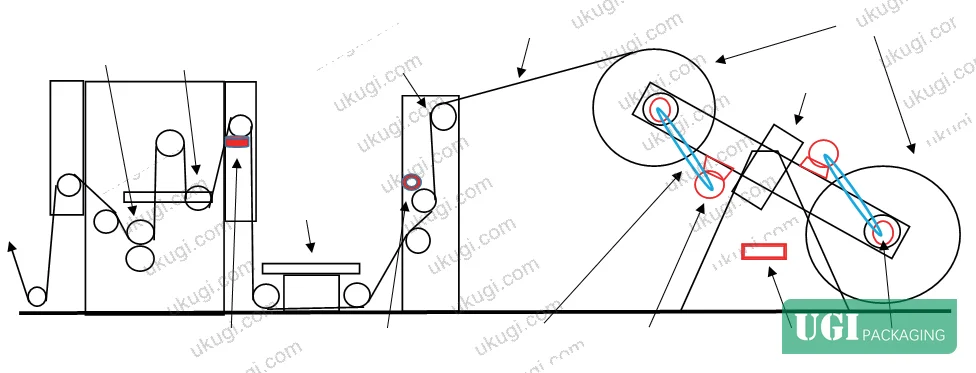
Closed-Loop Tension Control: How the Magnetic Powder System Maintains Register #
The constant-tension controller at the heart of the retrofitted system performs a straightforward but precisely executed comparison function: it continuously compares the tension setpoint (entered by the operator) against the live feedback value from the tension sensors, applies an internal calculation, and outputs an analog braking command to the magnetic powder brake. The brake responds to this command by modulating the magnetic field intensity in the powder gap, which changes the transmitted torque and therefore the braking force on the unwind mandrel.
The dual-sensor arrangement — two tension sensors mounted at both ends of the guide roller bearing housings — is worth noting. Single-point tension measurement on wide-web applications is vulnerable to skew loads; the two-sensor configuration detects asymmetric tension across the web width, which is a real failure mode when running board stocks with inconsistent caliper across the roll width.
The Hall-effect speed signal provides the controller with real-time mandrel velocity data. As roll diameter decreases during unwinding, the mandrel must accelerate to maintain constant web speed, and the braking torque requirement changes accordingly. Without speed feedback, even a well-tuned tension controller will allow tension excursions during acceleration and deceleration phases — exactly the condition that causes misregister in die-cutting and scoring operations.
Post-retrofit performance data collected over one full year of production confirmed: tension instability stoppages were eliminated, waste rates attributable to tension-related misregister dropped to zero, and maintenance burden on the unwind section was substantially reduced. The system architecture is also documented as structurally simpler than the original, with spare parts sourced domestically at a fraction of the previous imported-component cost.
For reference on how web tension interacts with substrate deformation properties during processing, ASTM D882 Standard Test Method for Tensile Properties of Thin Plastic Sheeting provides the standard test framework for characterizing how substrates respond to tensile load — directly relevant to setting appropriate tension setpoints for different stock types.
Substrate Compatibility and Tension Setpoint Selection for Digital and Finishing Lines #
The 400 N·m torque selection in this case was not arbitrary — it was matched to the actual web tension requirements of the paper stocks being processed. This is a calibration step that is frequently underspecified in equipment procurement and often left entirely to the machine operator’s intuition in production.
For buyers sourcing packaging from roll-fed lines — whether corrugated laminate, pressure-sensitive label stock, or coated folding carton board — the tension setpoint and the maximum braking torque of the unwind system define the practical substrate range the line can handle without introducing deformation or register errors. A system rated at 400 N·m with proper closed-loop control can accommodate a wide range of paper and board stocks, but the controller must be set correctly for each substrate type.
Industry observation worth noting: most procurement teams don’t realize that the tension control specification in an equipment data sheet describes the control system’s capability range, not its accuracy. A pneumatic system and a magnetic powder system can both be spec’d at the same maximum torque, but their dynamic response to tension excursions — how fast they correct, how much overshoot occurs — can differ by an order of magnitude. The magnetic powder brake responds in milliseconds to an analog signal change; a pneumatic system has compressibility lag built into every cylinder and line.
Web tension directly affects print-to-cut register in any inline finishing configuration. For digital print lines running variable data label work — a category that has expanded significantly with the growth of short-run and personalized packaging — maintaining tension within ±5% of setpoint through the entire web path is typically the threshold below which register error becomes visible at normal inspection distances. Lines with unstable tension commonly show creasing and die-cutting offset that appears random but is actually periodic, correlating with roll diameter change cycles.
ISO 12647-2:2013 Graphic technology — Process control for offset lithographic printing establishes process control principles that, while defined for offset, reflect the broader industry standard for what constitutes acceptable register and color variation tolerance in production printing — a useful reference point when setting acceptance criteria for digitally printed and finished packaging.
For conditioning and testing substrates before running them through tension-sensitive finishing equipment, ISO 187:1990 Paper, board and pulps — Standard atmosphere for conditioning and testing defines the standard environmental conditions that affect paper dimensional stability — a variable that interacts directly with web tension behavior during unwind.
Practical Guidance for Buyers #
If you’re sourcing roll-fed packaging — labels, folding cartons, paper bags, or specialty formats — ask your supplier directly how tension is controlled on their unwind systems. The correct answer involves a closed-loop feedback architecture, a specific sensor type, and a documented tension setpoint for each substrate class they run. “We have tension control” is not an answer. “We use a magnetic powder brake with dual load-cell feedback, rated at 400 N·m, controlled by a PLC-based constant-tension controller set to ±3% of setpoint for the paper weight you’re ordering” is an answer.
In supplier qualification, three of six finishing lines we evaluated at contract packaging facilities lacked any real-time tension feedback — they were running open-loop or semi-manual dancer systems on imported machines that had long since failed their original tension control components. The result showed up as periodic die-cut offset in the finished product that only became visible after lamination.
Ukugi operates as a Guangzhou-based OEM/ODM manufacturer producing labels, folding cartons, rigid boxes, flexible pouches, paper bags, and premium gift packaging — with full finishing capabilities including foil stamping, embossing, and UV coating. Our production engineering team can walk you through our web tension specifications and substrate qualification data for any format you’re sampling.
Tension control architecture isn’t glamorous, but it’s the difference between a supplier who can hold 0.3 mm die-cut register across a 10,000-unit run and one who can’t explain why your registration drifts halfway through the roll.
Need a custom formulation or sample? Request a quote from our team →
Supplier Qualification Questions #
- What is the rated braking torque of the magnetic powder brake units on your unwind mandrels, and is 400 N·m capacity confirmed for the paper weights in our substrate range?
- What type of tension sensor is installed on your roll-fed finishing lines — potentiometer-based dancer position, load-cell pressure sensor, or strain gauge — and can you show the sensor calibration record for the current production period?
- What is your documented tension setpoint tolerance for the substrate class in our order (e.g., ±5% or tighter), and do you have Hall-effect or encoder-based speed detection integrated into the tension control loop?
- During your last twelve months of production on this line, how many tension-related stoppages were recorded per shift, and what was the resulting waste rate attributable to die-cut or score register error from tension instability?
- Can you demonstrate that your constant-tension controller compares real-time sensor feedback against a fixed setpoint and outputs a direct analog signal to the brake — rather than relying on a proportional valve and pneumatic cylinder chain to execute the braking command?
Sourcing Checklist #
- ☐ Unwind tension control system uses a magnetic powder brake or equivalent closed-loop actuator, not open-loop pneumatic pad braking
- ☐ Braking torque capacity is rated at ≥400 N·m per mandrel for paper and board stocks in the 80–400 gsm range
- ☐ Tension feedback uses a pressure-based or load-cell sensor, not a dancer roller potentiometer as the sole feedback source
- ☐ Hall-effect or encoder-based speed detection is integrated into the tension control loop for mandrel velocity compensation
- ☐ Supplier can provide production stoppage logs showing tension-related downtime frequency for the past 12 months
- ☐ Die-cut register tolerance for finished samples falls within ±0.3 mm across a full roll run, verified by physical sample inspection
- ☐ Spare parts for the tension control system are documented as domestically sourceable, reducing long-term maintenance cost risk
Key Specifications Table #
| Parameter | Recommended Value | Verification Method |
|---|---|---|
| Magnetic powder brake torque rating | ≥400 N·m per unwind mandrel | Manufacturer spec sheet, confirmed against substrate tension requirements |
| Tension sensor type | Dual load-cell pressure sensors at guide roller bearing housings | Physical inspection of installation; request calibration certificate |
| Speed detection method | Hall-effect pulse detection on guide roller | Confirm pulse signal input is wired to constant-tension controller |
| Tension setpoint tolerance | ±3–5% of nominal setpoint throughout roll diameter reduction | Log data from constant-tension controller during production run |
| Feedback loop architecture | Closed-loop: sensor → controller → brake (max 3 components) | Request system schematic; reject if proportional valve + cylinder chain is present |
| Die-cut register accuracy | ≤0.3 mm offset across full roll | Physical measurement of finished samples at start, mid-roll, and end of roll |
Looking for a manufacturer that meets these specs? Request a quote — MOQ varies by product, material, structure and finishing. Product-specific MOQ is confirmed with each quotation.
References #
Data source: Closed-Loop Tension Control Retrofit for Roll-Fed Flatbed Die-Cutting Machines Using Magnetic Powder Brake Systems, P.-A. Xue et al., Journal of Applied Polymer Science, 2024
Frequently Asked Questions #
What is a magnetic powder brake and why is it better for web tension control than a pneumatic brake?
A magnetic powder brake uses the viscosity of a magnetizable powder between two rotating elements to transmit torque. The braking force is controlled directly by varying the electrical current to the magnetic coil — a fast, analog, and continuously variable response. A pneumatic brake relies on cylinders pushing pads against a disc, which introduces compressibility lag, mechanical wear variability, and multiple potential failure points in the control chain. For web tension applications where dynamic response matters, magnetic powder brakes respond in milliseconds; pneumatic systems typically lag by a full actuation cycle.
Why did replacing individual components in the original pneumatic system not fix the tension instability?
Because the fault was architectural. The original system had six cylinders, a proportional valve, a tension board, and a potentiometer — all in series. Replacing any single component still left five others that could introduce drift, lag, or failure. The only solution was replacing the entire architecture with a shorter, more direct control loop.
What braking torque rating should I look for when specifying a tension control system for folding carton board?
The case data here used 400 N·m, selected to match the specific paper stocks being processed. For heavier boards or wider webs, this figure scales up. The correct approach is to calculate the maximum web tension required for your heaviest substrate at maximum web width, then select a brake rated at ≥1.5× that figure to ensure stable control across the full roll diameter range. Don’t accept a system that was spec’d without documented calculation against your actual substrate range.
How does tension instability show up in finished packaging products?
It typically appears as periodic die-cut offset, inconsistent score depth, or misregister between print and cut that varies across the roll rather than being uniform. The periodicity often correlates with roll diameter change — tension tends to drift as the mandrel accelerates to maintain web speed with a reducing roll. On pressure-sensitive label stock, you may also see flagging or adhesive squeeze-out at the die-cut edge.
Does this type of tension control retrofit apply to digital print lines as well as finishing-only lines?
Yes. Any inline configuration where a web is unwound under tension — whether feeding into a digital press, a laminator, a die-cutter, or any combination — is subject to the same physics. For inline digital print finishing lines producing hologram security stickers or gift packaging solutions with tight register requirements, closed-loop tension control on the unwind is not optional equipment — it’s a prerequisite for production-grade register accuracy.
Published by ukugi.com Technical Team | Request a quote


