

Packaging Die Cutting: Tooling, Dielines, Samples and Defect Control
UGI Packaging manufactures the packaging and printed components covered in this article in our own factory. For packaging die cutting, we develop the specification and sample, operate the relevant printing, cutting, forming, finishing and assembly equipment, and inspect the approved result before packing. This connects each buyer decision to the way our factory actually produces and controls the job.
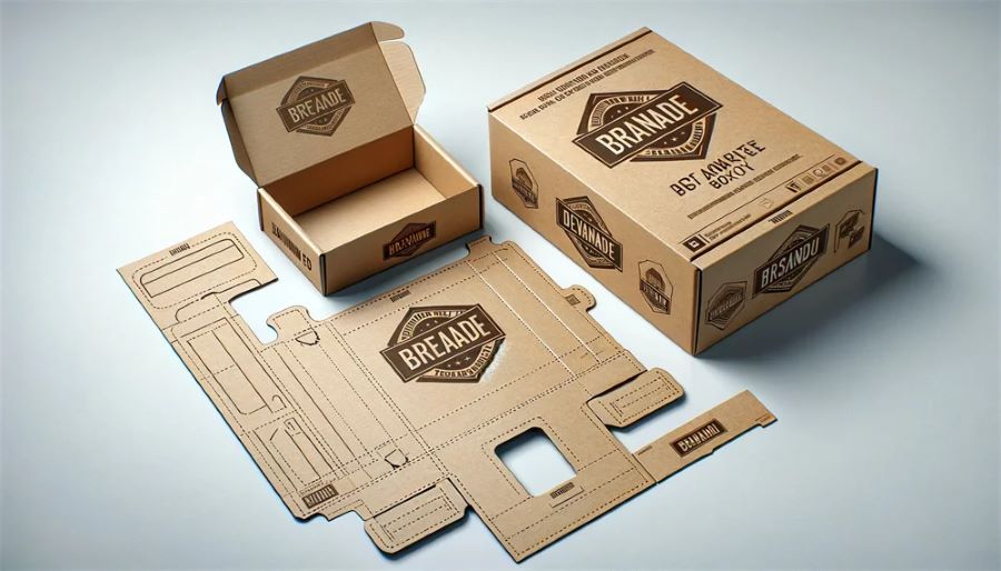
Packaging die cutting converts printed or unprinted sheet material into a blank with cut edges, creases, perforations and other features needed for assembly. A buyer should specify more than the outside shape: material, grain or flute direction, cut and crease rules, glue areas, waste removal, critical dimensions, artwork registration and the sample used for approval all affect the result.
Quick answer
Approve the dieline and material together. Identify which lines cut, crease, perforate or remain as reference marks; confirm product fit and folding sequence on a physical sample; and agree how cracking, incomplete cuts, dimensional drift, registration and stripping damage will be judged. Do not copy a dieline to a new material without checking crease and cutting behaviour.
Understand the converting operations
Cutting separates the blank from the sheet. Creasing creates a controlled folding zone. Perforation creates a tear or opening feature. Scoring, kiss cutting, embossing and waste stripping are different operations and should not be described with one generic “die cut” note.
The chosen route may use flatbed, rotary or digital/laser equipment, but method selection depends on material, geometry, run profile, edge requirements and available production capability. Our engineers select the method that fits the approved UGI Packaging production route.
Prepare a production-ready dieline
The dieline should show final dimensions, panel relationships, cut/crease/perforation legends, glue flaps, bleeds, safe zones, grain or flute direction, reference origin and version. Critical dimensions should be identified rather than assuming every line has the same importance.
For corrugated styles, the official FEFCO Code provides a common system for communicating basic packaging designs. A style code does not replace a dimensioned project dieline, material specification or performance test.
Match tooling and crease design to the material
Paperboard caliper, fibre direction, coating, lamination and moisture condition can change folding behaviour. Corrugated board adds flute direction and crushing risk. Wrapped rigid-box components use different converting and assembly logic from folding cartons; see the rigid box guide for that structure boundary.
Physical tooling creates setup and makeready cost. Digital cutting may avoid a conventional cutting die for some prototypes or runs, but speed, edge condition, crease reproduction and material compatibility still need review. The least expensive route depends on the complete job, not a universal run-size rule.
Coordinate artwork and finishes
Keep critical text, barcodes and decorative edges clear of uncertain fold or cut zones. Allow for realistic registration between print, foil, coating, embossing and the final blank. A finish can change surface friction or fold cracking, so the converting sample should represent the intended material stack when risk is high.
The updated packaging surface-finishes guide explains why foil, lamination and coatings must be assessed with folds and glue areas.
Send complete quotation inputs
Provide:
- a version-controlled dieline and finished dimensions;
- material, caliper and grain or flute direction;
- artwork with bleed and functional clear zones;
- quantities by artwork version;
- required cut, crease, perforation, window or opening features;
- downstream folding, gluing, filling and packing method;
- critical dimensions and product-fit requirements;
- sample or proof expectation; and
- defect and inspection requirements.
Cost categories may include tooling design, cutting die, crease matrix or counterpart, makeready, stripping tools, digital setup, material loss, special inspection and replacement tooling. Ask which items can be reused for unchanged reorders and under what documented conditions.
Approve samples in stages
A digital plotter or laser-cut prototype can confirm geometry and assembly but may not reproduce production creases or edge quality. A tooled blank using the intended material is more representative for fold behaviour, repeatability and stripping. A printed and finished sample is required when approval depends on registration or cracking at decorated folds.
Measure the assembled package with the product inserted. Record the sample material, dieline version, process substitutions and approved deviations.
Define production start and inspection
Start production after the dieline, material, artwork, tooling route, sample or proof, quantities, packing instructions and acceptance criteria are approved. A dieline revision after tooling can affect cost and timing.
Inspection may cover blank dimensions, cut completeness, crease position, fold direction, burrs or fibres, perforation function, nick marks, crushed flute, cracking, print-to-cut registration, glue-flap condition and contamination. Set project-specific tolerances from product fit and process evidence; do not import an arbitrary number from another box.
Prevent common die-cutting failures
Cracking often relates to material, grain direction, heavy coverage, finish or crease geometry. Incomplete cuts can come from setup, wear, material variation or pressure distribution. Poor stripping can tear edges or leave waste attached. Misregistration can result from artwork setup, sheet movement or cumulative process variation.
Prevention starts with a controlled dieline, correct material identification, representative sampling, first-off approval and periodic checks against an agreed master.
How UGI Packaging produces this work
Depending on the approved structure and artwork, our equipment route can include foil-stamping equipment. We develop the process specification and sample first, release the controlled production files, run the operations in the approved sequence, and inspect materials, registration, dimensions, surface condition, assembly and packing against the retained approval sample. Our engineers confirm project-specific materials, tooling and acceptance limits without shifting UGI Packaging’s manufacturing responsibility to an outside factory.
Use the UGI Packaging contact page to submit the dieline and product-fit requirements.
Frequently asked questions
Is laser cutting better than a physical die?
It is useful for some prototypes and geometries, but it is not universally better. Compare edge condition, crease needs, material response, speed, repeatability and total setup for the actual job.
Why does paperboard crack on a crease?
Possible causes include grain direction, material or coating brittleness, heavy ink or film, crease geometry and folding conditions. Test the intended material stack and fold direction.
Can I reuse an old dieline with a new board?
Only after review. A change in caliper, fibre direction, coating or structure can alter crease and fit performance even when the outline appears unchanged.
What should a die-cut sample prove?
It should prove geometry, assembly, product fit and relevant cut/crease features. If it uses substitute material or a non-production process, those limitations must be recorded.